6
A. FLAG ANGLES (AS REQUIRED):
A1. Quick Install (Q.I.) Flag Angles
A2. Fully Adjustable (F.A.) Flag Angles
B. JAMB BRACKETS (AS REQUIRED):
B1. Quick Install (Q.I.) Jamb Brackets
B2. Fully Adjustable (F.A.) Jamb Brackets
C. TRACK ROLLERS (AS REQUIRED):
C1. Short Stem Track Rollers
C2. Long Stem Track Rollers
D. GRADUATED END HINGES:
D1. Single Graduated End Hinges (S.E.H.), Anti-Pinch
D2. Double Graduated End Hinges (D.E.H.), Anti-Pinch
E. STACKED SECTIONS:
E1. Top Section
E2. Intermediate(s) Section
E3. Lock Section
E4. Bottom Section
F. TOP FIXTURE ASSEMBLIES (AS REQUIRED):
F1. Top Fixtures
G. STRUT(S) (AS REQUIRED):
G1. Strut (U - shaped)
H. DRAWBAR OPERATOR BRACKET (FOR TROLLEY OPERATED DOORS):
H1. Drawbar Operator Bracket
TRACKS (AS REQUIRED):
I1. Left Hand and Right Hand Horizontal Track Assemblies
I2. Left Hand and Right Hand Vertical Tracks
I3. Left Hand and Right Hand Riveted Vertical Track Assemblies
I4. Left Hand and Right Hand Angle Mount Vertical Track Assemblies
J. TORSION SPRING ASSEMBLY (AS REQUIRED):
J1. Left Hand and Right Hand Torsion Springs (As Required)
J2. Counterbalance Lift Cables
J3. Left Hand End Bearing Brackets (As Required)
J4. Right Hand End Bearing Brackets (As Required)
J5. Left Hand Cable Drum
J6. Right Hand Cable Drum
J7. Center Bracket (As Required)
J8. Center Bracket Bushing (As Required)
J9. Center Bearing Bracket (As Required)
J10. Torsion Shaft / Torsion Keyed Shaft (As Required)
J11. Torsion Keyed Shafts (As Required)
J12. Keys (As Required)
J13. Center Coupler Assembly (As Required)
J14. Set Collars (As Required)
K. REAR BACK HANGS:
K1. Left Hand and Right Hand Rear Back Hang Assemblies
L. BOTTOM CORNER BRACKETS:
L1. Left Hand and Right Hand Bottom Corner Brackets
C1.
C1.
C1.
C2.
D1.
D2.
E4.
E1.
E2.
E3.
F1.
G1.
H1.
Lower hole
of hole/
slot pattern
3rd
hole set
Top of vertical
track
B2. (Fully
Adjustable
Feature)
2nd
hole set
1st
hole set
B1. (Quick
Install
Feature)
3rd hole
set
Top of vertical
track
2nd
hole set
1st hole
set
Middle
hole
Bottom
hole
Top
hole
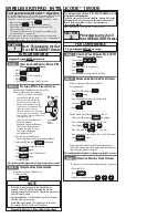
NOTE:
The illustrations shown on this page are general
representations of the door parts. Each specific door
models may have unique variations.
F1.
L1.
L1.
B1.
B2.
I2.
K1.
I3.
I1.
J1.
J10.
I4.
J6.
J4.
J2.
A1.
A2.
J9.
J12.
J14.
J7.
B1.
B2.
I2.
K1.
I3.
J7.
J2.
J1.
J3.
I4.
J5.
J12.
J14.
J7.
J11.
J11.
I1.
J13.
A2.
A1.
J9.
J8.
J12.
J12.
BREAKDOWN OF PARTS