


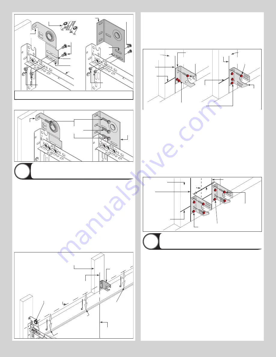
Bend back and fourth to seperate
the (2) end bearing brackets
(2) 3/8”-16
Hex nuts
(2) 3/8”-16 x 3/4”
Truss head bolts
Upper
slots
Lower
slots
Horizontal
track angle
Or
IMPORTANT:
THE END BEARING BRACKET’S LOWER SLOTS ARE USED ON DOORS WITH 12”
RADIUS TRACK; THE UPPER SLOTS ARE USED ON DOORS WITH 15” RADIUS TRACK.
(2) 3/8”-16
Hex nuts
(2) 3/8”-16 x 3/4”
Truss head bolts
Upper
slots
Lower
slots
Left hand
end bracket
Left hand
end bracket
Secure the top of the end bearing bracket to the jamb using 5/16” x 1-5/8” lag screw(s).
Repeat the same process for right hand side.
Jamb
5/16” x 1-5/8”
Lag screws
Or
Left hand
end bracket
Left
hand
end
bracket
Attaching Center Bracket to Wall
21
NOTE:
Refer to Package Contents / Breakdown of Parts, to determine which Center
Bracket(s) came with your door.
NOTE:
Drill 3/16” pilot holes into header for the lag screws.
NOTE:
Refer to Package Contents / Breakdown of Parts, to determine if your door came with
a coupler assembly. If your door came with a coupler assembly, the mounting surface needs
to be a minimum of 17” wide. The two center bearing brackets will need to be spaced 12” to
14” apart at the center of the door, as shown.
NOTE:
If your door came with (4) springs, each of the outer springs mounting surface will
need to be a minimum of 3” wide.
NOTE:
If needed, measure the diameter of your springs. If you have a one piece shaft with
3-3/4” diameter springs, they do not share center brackets and do not have a coupler as-
sembly.
First, locate the center of the door. Mark a vertical pencil line on the mounting surface above
the door, at the center. Measure from the center of the bearing, in one of the end bearing
brackets, downwards, to the top the door. Using that measurement, measure that distance
upwards from the top of the door to the mounting surface and mark a horizontal pencil line
which intersects the vertical pencil line.
Typical
center
bracket
Vertical
line
Equal distance (top of door
section to horizontal line)
Horizontal
line
Typical center
of left hand
end bearing
bracket
Jamb
Equal distance (top of door
section to horizontal line)
Center
of door
Spring mounting
pad (2” X 6”), White
Pine or denser.
IF YOUR DOOR DID NOT COME WITH A CENTER COUPLER ASSEMBLY OR TORSION
SPRINGS LESS THAN 3-3/4” ID:
Mark a vertical pencil line on the mounting surface above
the door, at the center. Align the edge of the center bracket with the vertical pencil line and
the center of the center bracket with the horizontal pencil line; this is to ensure the torsion
shaft is level between the center and end bearing brackets.
NOTE:
On some single spring doors, the spring can be longer than half the opening width. If
your spring is longer, then the center bracket must be mounted off center for the spring to fit
properly. Measure spring length adding room for spring growth during winding, to determine
appropriate center bracket location.
Center bracket
bushing assembly
5/16” x 1-5/8” Hex head lag screw (RED HEAD) or
5/16” x 2-1/2” Hex head lag screw (RED HEAD)
Vertical
line
Mounting
surface
(3” Minimum)
Horizontal
line
Vertical
line
Mounting surface
(3” Minimum)
Horizontal
line
Center
bearing
bracket
assembly
5/16” x 1-5/8” Hex head
lag screws (RED HEAD)
5/16” x 1-5/8” Hex head
lag screws (RED HEAD)
IF YOUR DOOR DID COME WITH A CENTER COUPLER ASSEMBLY OR 3-3/4” ID TOR-
SION SPRINGS:
Mark a vertical pencil line on the mounting surface above the door, at the
center. Split the difference up and position the (2) center bearing brackets apart from each
other. Mark two vertical pencil lines, one for each center bearing bracket onto the mounting
surface above the door.
NOTE:
If your door came with a center coupler assembly or if it utilizes 3-3/4” springs, the
springs will not share a center bracket.
NOTE:
If your door has (4) springs, split the distance between the center of the door and the
end bracket on each side to locate the intermediate center brackets.
Attach each of the center bracket(s) to the mounting surface, using 5/16” RED HEAD lag
screws, as shown.
IMPORTANT:
USE A 5/16” X 2-1/2” RED HEAD LAG SCREW INSTEAD OF THE 5/16” X
1-5/8” RED HEAD LAG SCREW IF MOUNTING SURFACE IS COVERED BY DRYWALL. THE LAG
SCREW MUST BE ATTACHED THROUGH THE BOTTOM HOLE OF THE CENTER BRACKET(S).
IF MOUNTING SURFACE IS A 2” X 6” BOARD INSTALLED ON TOP OF MASONRY, DRILL A
CLEARANCE HOLE IN MASONRY FOR THE 5/16” X 2-1/2” RED HEAD LAG SCREWS.
5/16” x 1-5/8” Hex head
lag screws (RED HEAD)
Vertical
line
Mounting surface
(17” Minimum)
Horizontal
line
Vertical line
† (2) Center bearing
brackets spaced 6” to
7” apart from the
center of the door.
Center
of
door
†12”
5/16” x 1-5/8” Hex head lag screw (RED HEAD) or
5/16” x 2-1/2” Hex head lag screw (RED HEAD)
Torsion Spring Assembly
22
NOTE:
Refer to the Package Contents and or Breakdown of Parts to determine if your door
came with a coupler assembly.
IMPORTANT:
RIGHT AND LEFT HAND IS ALWAYS DETERMINED FROM INSIDE THE BUILDING
LOOKING OUT.
IMPORTANT:
IDENTIFY THE TORSION SPRINGS PROVIDED AS EITHER RIGHT WOUND (RED
WINDING CONE), WHICH GOES ON THE LEFT HAND SIDE OR LEFT WOUND (BLACK WINDING
CONE), WHICH GOES ON THE RIGHT HAND SIDE.
IMPORTANT:
ON SINGLE SPRING APPLICATIONS, ONLY A LEFT WOUND (BLACK WINDING
CONE), IS REQUIRED.
NOTE:
The set screws used on all winding cones and cable drums are colored red. DO NOT
identify right and left hand by the set screw color.
IF YOU DON’T HAVE A COUPLER ASSEMBLY:
Facing the inside of the door, lay the torsion
shaft / torsion keyed shaft on the floor. Lay the torsion spring with the black winding cone
and the black cable drum at the right end of the torsion shaft / torsion keyed shaft. Lay the
torsion spring with the red winding cone and the red cable drum at the left end of the torsion
shaft / torsion keyed shaft. Slide the center bracket bearing onto the torsion shaft / torsion
keyed shaft followed by the torsion springs and cable drums.
IMPORTANT:
THE CENTER BRACKET BEARING, TORSION SPRINGS, AND CABLE DRUMS
MUST BE POSITIONED, AS SHOWN.
15


