background image

20

Need help or have any questions?  Call us at 1-714-963-0329 or send us an email to [email protected]

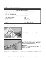
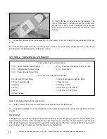
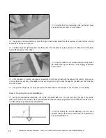
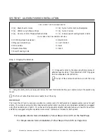
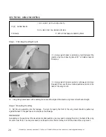
With the adhesive tape securely in place, use a hair dryer

to shrink the heat-shrink material tight across the entire wing,
both top and bottom.

WARNING

Work slowly and use only enough heat to shrink the heat-
shrink material.  Excessive heat could melt the foam wing.

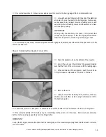
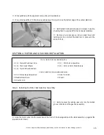
Carefully apply the leading and trailing edge pieces of

reinforcement board to the wing making sure they're centered
over the centerline.  Notice that the pieces are scored to make
it easier to bend around the wing.

IMPORTANT

The middle portion of one piece of reinforcement board is
thinner than the other piece.  

The piece with the thinner

center section is for the leading edge.

Step 2:  Installing the Plastic Wing Mount

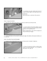
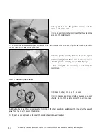
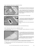
Using a ruler and a pencil, measure and draw a center-

line on top of the wing mount, at both the front and the back.

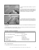
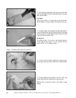
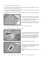
Using a modeling knife, carefully cut a hole in the wing

mount using the factory-made scribe lines as a guide.

This hole will allow the aileron servo lead(s) to pass

through.

Summary of Contents for Crazy MAX EP

Page 1: ...ea whose membership includes qualified instructors If there is no hobby shop in your area we recommend that you contact the AMA at the address below They will be able to help you locate a flying field...

Page 2: ...of the purchased kit In that Wattage has no control over the final assembly or material used for final assembly no liability shall be assumed for any damage resulting from the use by the user of the f...

Page 3: ...work table with brown paper or a soft cloth both to protect the table and to protect the parts Keep a couple of small bowls or jars handy to put the small parts in after you open the accessory bags We...

Page 4: ...y 1 2oz or less Most four channel micro receivers will be a good choice If you plan on using the Hitec 555 Micro receiver we suggest removing the case to reduce the receiver s weight If you do remove...

Page 5: ...us MRX 4 Micro Receiver uses a single conversion Hitec crystal A dual conversion crystal will not work with it We have organized the parts as they come out of the box for easier identification during...

Page 6: ...WING MOUNTING ASSEMBLIES 1 Molded Plastic Wing Mount 1 3mm x 60mm Wood Dowel 1 3mm x 70mm Wood Dowel 1 Wing Reinforcement Board 2 Parts 2 180mm Long Adhesive Strips 2 Rubber Bands MISCELLANEOUS ITEMS...

Page 7: ...5 9mm 3 4 19 0mm 1 25 4mm 2 50 8mm 3 76 2mm 6 152 4mm 12 304 8mm 18 457 2mm 21 533 4mm 24 609 6mm 30 762 0mm 36 914 4mm METRIC CONVERSION CHART IMPORTANT The soldering iron and solder listed above are...

Page 8: ...ING SUPPLIES Pencil Paper Towels Rubbing Alcohol NHP Epoxy Mixing Sticks NHP Epoxy Mixing Cups Step 1 Installing the Truss Decal Using a pair of scissors cut out the fuselage truss decal along its out...

Page 9: ...adhere the reinforcement board to the fuselage To align it properly the front edge of the board should be even with the back of the plywood motor mount and the sides of the board should follow the sid...

Page 10: ...s Reinforcement Spar 1 Prebent Elevator Joiner Wire SECTION 2 HORIZONTAL STABILIZER 1 Elevator Reinforcement Board 2 Parts 1 Decal Sheet YOU LL NEED THE FOLLOWING SUPPLIES 220 Grit Sandpaper w Sanding...

Page 11: ...king tape and carefully sand the ends of the spar even with the ends of the stabilizer Place the prebent wire on the bottom of the elevator Center the wire over the middle of the elevator making sure...

Page 12: ...e there is a 1 16 gap between them Use the guide marks on the ends of the hinge decal to help you set the proper hinge gap Step 4 Mounting the Horizontal Stabilizer Using a ruler and a pencil draw a c...

Page 13: ...ar should be even with the back edge of the fuselage and the centerline you drew on top of the stabilizer should be centered over the middle of the fuselage When satisfied with the alignment hold the...

Page 14: ...arts After the decal is in place use a pair of scissors to trim the decal flush with the edges of the rudder Once you ve trimmed the decal use 220 grit sandpaper with a sanding block to lightly sand t...

Page 15: ...ol and hold the stabilizer in place until the epoxy sets up 1 Phillips Head Screwdriver Needle Nose Pliers Electric Drill YOU LL NEED THE FOLLOWING PARTS 1 Prebent Main Gear Wire 2 Main Gear Wheels 2...

Page 16: ...gear box assembly back into place and realign it Install and tighten the three 3mm x 12mm wood screws to hold the gear box assembly securely to the fuselage Don t overtighten the screws or you might...

Page 17: ...rvos output shafts should face toward the front of the fuselage Install the rubber grommets and brass collets onto each of the servo mounting lugs Mount the servos using the servo mounting screws prov...

Page 18: ...the servo horn and the elevator centered use a pencil to draw a mark on the pushrod wire where it crosses the hole that is 1 4 out from the center of the servo horn Place a single arm servo horn onto...

Page 19: ...PPLIES Step 1 Joining the Wing Panels After the epoxy has cured apply one piece of adhesive tape on the bottom of the wing over the center section joint Turn the wing over and apply the second piece o...

Page 20: ...ent board to the wing making sure they re centered over the centerline Notice that the pieces are scored to make it easier to bend around the wing IMPORTANT The middle portion of one piece of reinforc...

Page 21: ...onto the bottom of the wing Remove the wing mount from the wing Using 220 grit sandpaper very carefully lightly roughen the gluing surfaces of both the plastic wing mount and the bottom of the wing Us...

Page 22: ...ire Cutters Needle Nose Pliers Excel Modeling Knife Electric Drill 1 16 Drill Bit Ruler Pencil Using a modeling knife cut away and remove the foam from inside the hole you cut previously in the plasti...

Page 23: ...eat the procedures above to install the second aileron servo into the other half of the wing Step 3 Installing the Aileron Pushrods Separate Servo Setup Using a modeling knife cut a thin 1 4 long slot...

Page 24: ...provided with your servo to secure the servo horn into place You will need to enlarge the hole in the servo arm using a 1 16 drill bit so that the pushrod wire will fit through Repeat the previous pr...

Page 25: ...he receiver Plug the ESC lead into the receiver and the flight battery into the ESC Turn on the radio system and center the servo using the trim lever on the transmitter Thread one nylon clevis onto e...

Page 26: ...t away and remove the plastic from over the two molded pushrod exit slots in the back of the wing mount Using 220 grit sandpaper with a sanding block sand the edges of the plastic wing mount smooth an...

Page 27: ...ling Knife Scissors K S 30 Watt Soldering Iron Kester Solder Thread one 3mm hex nut onto the propeller shaft and tighten it by hand until it will not thread on any further Slide the propeller onto the...

Page 28: ...rottle lead through the front hole in the fuselage and plug it into the proper slot in the receiver If the motor leads on your ESC do not match the motor leads on the motor you will need to remove the...

Page 29: ...two 1 4 diameter air intake holes in the front of the plastic wing mount to allow cool air to pass over the flight battery This will keep the battery from over heating Step 5 Installing the Pilot Fig...

Page 30: ...As you move the C G further aft you may find you need to either trim the elevator down slightly or add about 2 degrees of downthrust in the motor to prevent the airplane from climbing Balance the Cra...

Page 31: ...hole through the skid Carefully lift the airplane up by the two pieces of string Watch how the wing reacts If one side of the wing drops that side is heavier than the other To correct this stick a sma...

Page 32: ...endations are not set in stone Feel free to make adjustments to suit your flying style Have fun experimenting FLAPERONS FOR SLOW FLIGHT The Crazy Max will fly pretty slowly set up as is It ll fly even...

Page 33: ...not suggest storing your airplane in an extremely hot environment like the back of your car in direct sunlight for any length of time The extreme heat could cause the foam to melt and possibly damage...

Page 34: ...ol throws until you are confident flying the airplane You will find that at full power the Crazy Max is quite fast so you have to be on top of it Most all types of aerobatics can be done with the Craz...

Page 35: ...our Customer Service Department to resolve the problem Yes No 7 Was any of the assembly difficult for you If yes please explain Yes No ________________________________________ _______________________...

Page 36: ...Fold along dotted line Fold along dotted line Global Hobby Distributors Attn Customer Service 18480 Bandilier Circle Fountain Valley CA 92728 8610 Post Office will not deliver without proper postage _...

Reviews: