17
Visit our website at http://watt-age.globalhobby.com for information on other Wattage products
❑
Magnum Z-Bend Pliers
❑
Wire Cutters
❑
Needle Nose Pliers
❑
Excel Modeling Knife
YOU'LL NEED THE FOLLOWING PARTS:
❑
{2} 1.5mm x 400mm Threaded Pushrod Wires
❑
{2} Nylon Control Horns w/Backplates
SECTION 5: ELEVATOR & RUDDER PUSHROD INSTALLATION
❑
{2} Nylon Clevises
YOU'LL NEED THE FOLLOWING SUPPLIES:
❑
Electric Drill
❑
1/16" Drill Bit
❑
Ruler
❑
Pencil
Step 2: Installing the Servos
❑
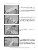
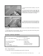
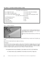
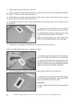
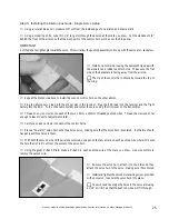
Test fit your two micro servos into the rear hole in the
fuselage. If necessary, use a modeling knife to enlarge the
hole to accommodate your particular servos.
☛
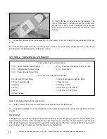
Both of the servos' output shafts should face toward the
front of the fuselage.
❑
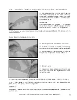
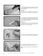
Install the rubber grommets and brass collets onto each of the servo mounting lugs.
❑
Mount the servos using the servo mounting screws provided with your servos. To make it easier to install the screws,
use the tip of your modeling knife to make small pilot holes in the reinforcement board.
❑
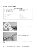
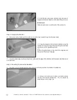
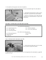
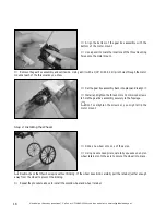
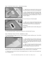
Push one control horn through each die-cut hole in the rudder and the elevator. The tip of the elevator control horn
should face the top of the elevator and the tip of the rudder control horn should face the side opposite the elevator
control horn.
Step 1: Installing the Control Horns
❑
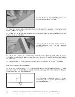
Making sure that the
flat portion
of the backplates face
away
from the control surfaces, push the backplates over the
ends of the control horns until you hear them "click" firmly
into place.

