Waterlogic Commercial Products, LLC
11710 Stonegate Circle
Omaha, NE 68164
(800) 288-1891
www.waterlogic.us
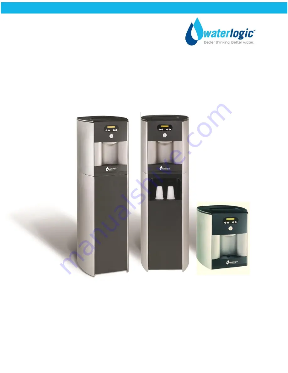
WL500 – Sparkling
OPERATING, INSTALLATION, AND SERVICE MANUAL
Page 1: ...Waterlogic Commercial Products LLC 11710 Stonegate Circle Omaha NE 68164 800 288 1891 www waterlogic us WL500 Sparkling OPERATING INSTALLATION AND SERVICE MANUAL...
Page 2: ...e TABLE OF CONTENTS Features and Benefits 3 Certifications 4 Introduction 5 Safety Alert Symbols 5 Safety Precautions 6 Warranty 7 Model and Part Designations 8 Specifications 8 Layout Drawing and Par...
Page 3: ...Sensor and Drip Tray Full Fault Mode that halts supply to prevent overflow and sounds alarm to reduce accident potential Child Safeguard WL500 requires selection followed by main dispense and defaults...
Page 4: ...o ANSI UL 399 Standard for Drinking Water Coolers BPA Free Waterlogic tests for BPA and declares that all of its products are Bisphenol A FREE and contain no harmful BPA plastics Waterlogic is certifi...
Page 5: ...aterlogic and its affiliates are protected by patents issued or pending in the United States and other countries Waterlogic reserves the right to change the specifications referred to in this literatu...
Page 6: ...ter the system The system is designed for the supplemental bactericidal treatment of either treated and disinfected public drinking water or other drinking water which has been tested and deemed accep...
Page 7: ...ing documentation to Waterlogic for evaluation The form is available at www waterlogic us Supporting documentation must include but is not limited to proof of purchase installation date failure date a...
Page 8: ...x 18 in x 10 in AK 0007 32 in x 12 in x 7 in Shipping Weight Dry 70 lb 32 kg AK 0005 35 lb AK 0007 9 lb Rated Service Flow Rated Capacity Service Life 0 5 gpm 1 89 lpm 2 000 Gallons or 6 months Same...
Page 9: ...nly BIOCOTE WL LOGO same as PL 1222 10 7074 8 PL 1094 Side Panel Silver Plastic LH RH 10 7072 9 ST 8094 A Back Metal Panel 10 7051 10 EL 5005 Switch Heater Compressor Green I ON O OFF 10 3009 11 EL 50...
Page 10: ...spense Button For Sparkling Water Press Sparkling Button 2 followed by the Main Dispense Button For Hot Water Press Hot Button 3 followed by the Main Dispensing Button For Extra Hot Water Press Extra...
Page 11: ...Revision 1 1 Page 11 WL500 FLOW DIAGRAM...
Page 12: ...r on the display and cold water will be dispensed when the Main Dispense Button is pressed Selecting COLD Button 1 and then pressing the Main Dispense Button opens Solenoids 2 and 4 which allows suppl...
Page 13: ...the Main Dispensing Button for Premium Sparkling Water The unit will default back to COLD water after 3 seconds unless the Default Set is changed to Sparkling See Programming Section When the Main Dis...
Page 14: ...imal sparkling water is generated with cold water under 46o F WL500 Sparkling Level Sensor Probe requires inspection and service See Service Section WL500 Sleep Mode The WL500 has programmable sleep m...
Page 15: ...rade Language English The display will read in English Default is English Spanish The display will read in Spanish French Etc The display will read in French and many others Flow Counter Liters 4000 9...
Page 16: ...ntil the option Language appears on the display 3 Press Button No 3 to select the Language option 4 Press Button No 2 repeatedly to scroll down through the languages until Spanish is displayed 5 Press...
Page 17: ...Close the regulator outlet valve and secure in the base cabinet 5 Route a inch pipe from the outlet fitting of the CO2 regulator through the knock out up to the CO2 IN bulkhead fitting on the back of...
Page 18: ...the Waterlogic WL500 and check exterior for damage WARNING WL500 IS HEAVY Use proper lifting aids and handling techniques to avoid injury Use assistance as single person lift could cause injury Always...
Page 19: ...SONAL PROTECTIVE EQUIPMENT Always ensure proper ventilation and use proper personal protective equipment such as gloves and eye protection when using chemicals Refer to Material Safety Data Sheet for...
Page 20: ...ion Required The first 2 or 3 gallons of water will contain concentrated sanitizer Use extreme care Fill the Sparkling Chamber with Sanitizer 20 The sanitizer solution will be injected into the sparkl...
Page 21: ...nce the compressor starts the fan condenser also will start Verify the fan has started by feeling for the discharge of air at the rear grill of the machine Heat exchange is a signal that the refrigera...
Page 22: ...sing personnel and equipment drains catch basin etc to scalding hot water Disable Cold and Hot Tanks 1 Turn off the green power switch to disable the heater and compressor 2 Dispense 2 liters of water...
Page 23: ...e PRV on top of the sparkling chamber to vent the system May remove top cover to access 21 Remember to close the Pressure Relief Valve once all pressure is relieved 22 Remove the CO2 supply line from...
Page 24: ...Never expose to freezing temperatures Ensure there is adequate clearance around the unit to allow refrigeration system condenser to dissipate heat Warmer environments require more clearance around the...
Page 25: ...e dispensing faucet press the hot button Button 3 followed by the main dispensing button until a continuous flow of water is obtained Once a continuous flow is obtained release the main dispensing but...
Page 26: ...ater below 46O F into the chamber This provides Premium Sparkling Water Sample the sparkling water to ensure it meets expectation 16 Check the unit for any leaks External Leak Protection is always rec...
Page 27: ...abrasive cloth to clean Inspect the Quartz Sleeve O ring CT 2006 for wear or damage and replace as necessary 4 Test UV lamp and UV sensor CDS is working by removing the sensor from the retaining nut a...
Page 28: ...ONAL PROTECTIVE EQUIPMENT REQUIRED Always ensure proper ventilation and use rubber or nitrile gloves and eye protection when using chemicals Refer to Material Safety Data Sheet for specific requiremen...
Page 29: ...embly Part Number is HT 3021 INN 10 7082 Sparkling Chamber Level Sensor Probe Assembly CT 2023 WL500 Sparkling chamber has a level sensor probe that needs to be maintained and descaled at every filter...
Page 30: ...Revision 1 1 Page 30 WL500 MAIN PARTS DRAWING...
Page 31: ...p Fixing Rubber Silicon 10 3004 16 CT 2045 UV Lamp 8W with wires 10 7020 17 CT 2006 O ring Black Quartz Sleeve 10 2500 18 CT 2002 Quartz Sleeve D310mm for 8W Lamp 10 1400 19 CT 2001 C Cold Tank Retain...
Page 32: ...2039 A CT 2028 Drain valve Cap Only for both 1 4 5 16 Drains CT 2028 48 PU 4028 JG Bulkhead Connector Union 1 4 1 4 PI1208S 10 3067 49 PL 1094 Side Panel Silver 10 7072 50 CT 2035 D AQ Q Pump With Co...
Page 33: ...Revision 1 1 Page 33 WL500 WETTED PARTS DRAWING...
Page 34: ...E 08 BI 1000F B 19 1054 17 PU 4008 JG Equal Elbow Connector 1 4 PI0308S PU 4008 18 PU 4008 JG Equal Elbow Connector 1 4 PI0308S PU 4008 19 PU 4031 JG LLD PE Tube Blue O D 1 4 PE 08 BI 1000F B 19 1054...
Page 35: ...DPE Tube Blue 8mm PE 0806 100M B 10 3062 51 PL 1088 Stainless Steel Insert for Faucet WL850 Sparkling with SUS 10 2701 52 PL 1011 Faucet HC CA 10 2700 53 CT 2007 Natural Faucet O Ring Silicon White 10...
Page 36: ...utes and there is not a signal from the level sensor to shut off the pump This is a safety feature to prevent the pump from being damaged When operating properly it should take about 1 1 2 minutes for...
Page 37: ...Revision 1 1 Page 37 WL500 ELECTRICAL DIAGRAM DANGER HIGH VOLTAGE ELECTRICAL HAZARD PCB Printed Circuit Board contains High Voltage Only trained and qualified technicians should attempt live testing...
Page 38: ...nt lip has only 2 holes Step 3 Fasten the front door and frame assembly to the front edges of the top and base panels Top panel and base panel edges fit inside of door assembly edges Screw Locations 5...
Page 39: ...ar Align the side panels using the plastic tabs which will protrude through the metal frame WL500 to Base Cabinet Attachment Point Use locking screw provided or ST 8016 adjustable foot Step 5 Front Bl...
Page 40: ...l into the base cabinet Note that this task will require a little maneuvering of the insert panel for proper alignment Take care not to break the plastic tabs on the insert panel Step 3 Fasten the cup...