9
User guide for IP Weather Station WARIO ME13
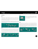
Step 5
The actual installation of the weather station, i.e. the attachment of the main telescopic
mounting pole to the prepared console, is done by attaching it by clips to the console (part
10). Orientation of the whole weather station in space relative to geographical position and
the actual sensors is very important. Tight fixation in all directions is important and it should
also be placed perpendicularly in all directions. If the weather station is not fixed tightly or is
not placed perpendicularly, measurements might be inaccurate.
Step 6
Mechanically verify that the weather station is tightly fixed in its location and set its orientation
so that the label W of the wind direction sensor faces the West and the radiation shield
of the combined sensors is unshaded and facing South (Northern hemisphere) or North
(Southern hemisphere). Then use tightening belts (part 11) to attach the cables leading to
the control unit of the weather station. If the data cable goes over parts of the consoles or
other features in the interior, it must always be tightly attached. The data cable is resistant
against UV light and is intended for outdoor use. Make sure all parts are tightly fixed and that
the cables are well attached. Otherwise measurements might be inaccurate, errors arise or
it could even lead to the malfunctioning of the whole station.
Step 7
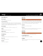
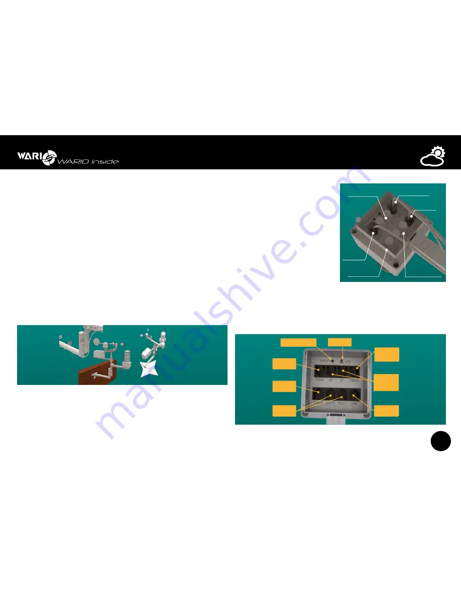
Connect all the cables to the control unit. The weather station uses the RJ11 and RJ45
connectors for connection and communication between the control unit and the sensors.
Connectors for data communication and WBUS interface are different from these and must
not be interchanged.
z
Connect the wind speed and wind
direction sensor to the receptacle
labeled as “WIND”
z
connect the rain gauge to the
receptacle labeled as “RAIN”. This
connector also includes connection
for heated rain gauge, which is
optional.
z
Data cable from the PoE adapter
connect to the receptacle labeled
“LAN”.
z
Connect the optional temperature
or temperature/humidity sensors to
the receptacles labeled “S1 or S2”.
z
Connect the relay outputs to receptacles “OUT1 or OUT2”.
z
Connect the WBUS interface data cable to the receptacle labeled “WBUS”.
Step 8
1
1
1
1
1
2
2
2
3
4
6
5
2
7
8
3
4
6
5
2
8
7
10
11
11
3
2
3
4
2
3
2
W
WBUS
Additional
devices
1 –
2 –
3
RS-485 B
4 VNAP
5 VNAP
6
RS-485 A
7 GND
8 GND
LAN
POE
7
Connector
for radiation shield
3
2
4
3
4
6
5
2
5
9
6
Connector
for connecting
rain gauge
Signal LED diode
Reset button
Resets weather station to factory defaults
Connector
for connecting
additional devices
Connector
for connecting
relay outputs
Data and power
cable connector
Connector
for connecting
external temperature
and humidity sensors
Connector
for connecting
wind speed and wind
direction sensor
max.25 m
LAN
IP Weather Station
WARIO ME13
WAN
Internet
230V
12
Rain gauge
7
Wind speed and
wind direction sensor
POE adapter
data cable
Optional temperature
and humidity sensors
WBUS interface data
cable connection
Control relay outputs
OUT1
OUT2
COM
NO
central relay pole
power on relay pole
13
13
9
9
9
N
S
W
E
1
1
1
1
1
2
2
2
3
4
6
5
2
7
8
3
4
6
5
2
8
7
10
11
11
3
2
3
4
2
3
2
W
WBUS
Additional
devices
1 –
2 –
3
RS-485 B
4 VNAP
5 VNAP
6
RS-485 A
7 GND
8 GND
LAN
POE
7
Connector
for radiation shield
3
2
4
3
4
6
5
2
5
9
6
Connector
for connecting
rain gauge
Signal LED diode
Reset button
Resets weather station to factory defaults
Connector
for connecting
additional devices
Connector
for connecting
relay outputs
Data and power
cable connector
Connector
for connecting
external temperature
and humidity sensors
Connector
for connecting
wind speed and wind
direction sensor
max.25 m
LAN
IP Weather Station
WARIO ME13
WAN
Internet
230V
12
Rain gauge
7
Wind speed and
wind direction sensor
POE adapter
data cable
Optional temperature
and humidity sensors
WBUS interface data
cable connection
Control relay outputs
OUT1
OUT2
COM
NO
central relay pole
power on relay pole
13
13
9
9
9
N
S
W
E


