8
User guide for IP Weather Station WARIO ME13
Installation
Step 1
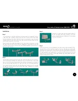
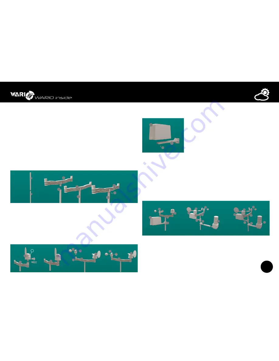
It is recommended to begin the installation with the main telescopic mounting pole (part
1) and plastic wind speed and wind direction arm (part 2). Connect the first part of the
telescopic mounting pole with the plastic wind sensor arm using the locking mechanism
and making sure it is locked on both sides. Then fix the position of both parts using nuts and
bolts in order to make sure it is well fixed.
If you are using the multi-functional Meteo console, the procedure is the same as if using
the plastic wind sensor arm (part 2). This type of installation is recommended if you wish
to measure wind speed and wind direction at a different height than for example the air
temperature and humidity.
1
1
1
1
1
2
2
2
3
4
6
5
2
7
8
3
4
6
5
2
8
7
10
11
11
3
2
3
4
2
3
2
W
WBUS
Additional
devices
1 –
2 –
3
RS-485 B
4 VNAP
5 VNAP
6
RS-485 A
7 GND
8 GND
LAN
POE
7
Connector
for radiation shield
3
2
4
3
4
6
5
2
5
9
6
Connector
for connecting
rain gauge
Signal LED diode
Reset button
Resets weather station to factory defaults
Connector
for connecting
additional devices
Connector
for connecting
relay outputs
Data and power
cable connector
Connector
for connecting
external temperature
and humidity sensors
Connector
for connecting
wind speed and wind
direction sensor
max.25 m
LAN
IP Weather Station
WARIO ME13
WAN
Internet
230V
12
Rain gauge
7
Wind speed and
wind direction sensor
POE adapter
data cable
Optional temperature
and humidity sensors
WBUS interface data
cable connection
Control relay outputs
OUT1
OUT2
COM
NO
central relay pole
power on relay pole
13
13
9
9
9
N
S
W
E
Step 2
Next install the wind direction (part 3) and wind speed sensor (part 4). It is necessary to
make sure that when installing the weather direction sensor, the label “W” on the actual
sensor is in the direction pointing outwards from the plastic mounting arm and connect
the sensor by the locking mechanism to it. Then use nuts and bolts to fix them permanently.
Next connect the wind speed sensor (part 4) with the plastic mounting arm. Just like with
the wind direction sensor, first use the locking mechanism and subsequently use nuts and
bolts for tight connection.
1
1
1
1
1
2
2
2
3
4
6
5
2
7
8
3
4
6
5
2
8
7
10
11
11
3
2
3
4
2
3
2
W
WBUS
Additional
devices
1 –
2 –
3
RS-485 B
4 VNAP
5 VNAP
6
RS-485 A
7 GND
8 GND
LAN
POE
7
Connector
for radiation shield
3
2
4
3
4
6
5
2
5
9
6
Connector
for connecting
rain gauge
Signal LED diode
Reset button
Resets weather station to factory defaults
Connector
for connecting
additional devices
Connector
for connecting
relay outputs
Data and power
cable connector
Connector
for connecting
external temperature
and humidity sensors
Connector
for connecting
wind speed and wind
direction sensor
max.25 m
LAN
IP Weather Station
WARIO ME13
WAN
Internet
230V
12
Rain gauge
7
Wind speed and
wind direction sensor
POE adapter
data cable
Optional temperature
and humidity sensors
WBUS interface data
cable connection
Control relay outputs
OUT1
OUT2
COM
NO
central relay pole
power on relay pole
13
13
9
9
9
N
S
W
E
Step 3
1
1
1
1
1
2
2
2
3
4
6
5
2
7
8
3
4
6
5
2
8
7
10
11
11
3
2
3
4
2
3
2
W
WBUS
Additional
devices
1 –
2 –
3
RS-485 B
4 VNAP
5 VNAP
6
RS-485 A
7 GND
8 GND
LAN
POE
7
Connector
for radiation shield
3
2
4
3
4
6
5
2
5
9
6
Connector
for connecting
rain gauge
Signal LED diode
Reset button
Resets weather station to factory defaults
Connector
for connecting
additional devices
Connector
for connecting
relay outputs
Data and power
cable connector
Connector
for connecting
external temperature
and humidity sensors
Connector
for connecting
wind speed and wind
direction sensor
max.25 m
LAN
IP Weather Station
WARIO ME13
WAN
Internet
230V
12
Rain gauge
7
Wind speed and
wind direction sensor
POE adapter
data cable
Optional temperature
and humidity sensors
WBUS interface data
cable connection
Control relay outputs
OUT1
OUT2
COM
NO
central relay pole
power on relay pole
13
13
9
9
9
N
S
W
E
Next step is to complete the plastic rain gauge arm (part 5)
and the rain gauge itself (part 6). Connect both parts
together using the locking mechanism and fix them tightly
by a small screw (part 9).
Step 4
Attach the entire plastic arm and rain gauge to the main telescoping mounting pole. Then
also attach the metal arm with the control unit and the combined sensor to the main
mounting pole, facing upwards. If you want to increase the overall height of the weather
station from the install console, extend the telescopic mounting pole with the other part of
it. Tighter attachment can be achieved by screwing the control unit arms together. It is not
always necessary to use both parts of the main mounting pole and installation can also be
performed using just one of them.
1
1
1
1
1
2
2
2
3
4
6
5
2
7
8
3
4
6
5
2
8
7
10
11
11
3
2
3
4
2
3
2
W
WBUS
Additional
devices
1 –
2 –
3
RS-485 B
4 VNAP
5 VNAP
6
RS-485 A
7 GND
8 GND
LAN
POE
7
Connector
for radiation shield
3
2
4
3
4
6
5
2
5
9
6
Connector
for connecting
rain gauge
Signal LED diode
Reset button
Resets weather station to factory defaults
Connector
for connecting
additional devices
Connector
for connecting
relay outputs
Data and power
cable connector
Connector
for connecting
external temperature
and humidity sensors
Connector
for connecting
wind speed and wind
direction sensor
max.25 m
LAN
IP Weather Station
WARIO ME13
WAN
Internet
230V
12
Rain gauge
7
Wind speed and
wind direction sensor
POE adapter
data cable
Optional temperature
and humidity sensors
WBUS interface data
cable connection
Control relay outputs
OUT1
OUT2
COM
NO
central relay pole
power on relay pole
13
13
9
9
9
N
S
W
E


