Rev. 1.1
Assembly Instructions - Dosing Valve Station 9741970.0x
Page 13 of 31
Walther Systemtechnik GmbH
– D 76726 Germersheim
Telefon: +49 (0)7274-7022-0 Telefax: +49 (0)7274-7022-91
http://www.walther-2000.de
4 Commissioning
4.1 Mounting and Installation
IMPORTANT
We recommend a front-end maintenance unit for the control air.
4.2 Adjusting the Incomplete Device
IMPORTANT
Make sure that the air pressure for the control air is at approx. 6 bar. This guarantees
an optimum function of the valves.
The material inlet pressure should not rise above 200 bar. Check also the pressure
ratio of the feeder pump. A pressure reduction valve will help you to easily control the
supply pressure (a pressure reduction valve is an advantage but not mandatory, if
pressure stays below 200 bar).
IMPORTANT
All dosing valves will be checked at our factory before delivery. It may therefore hap-
pen that some residues from the test media remain in the valve.
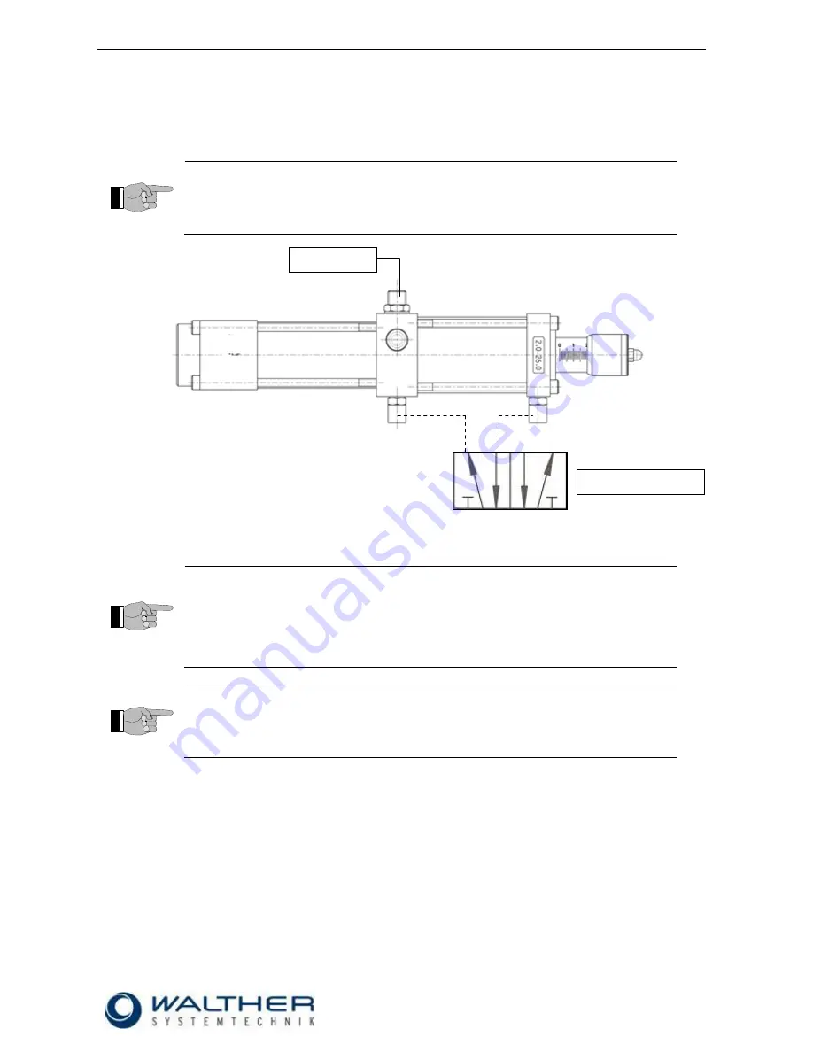
1) Fill lubricant supply hoses with lubricant before connecting a dosing valve (ventilating). Then connect
supply hoses and control air according to layout.
2) Set maximum dosing amount (turn adjusting sleeve to the far outside) when first starting the device.
3) If adjusting sleeve cannot be turned, operate rerouting valve. You can now operate the adjusting
sleeve.
4) After the first release of lubricant, the desired dosing quantity can be set through the adjusting
sleeve.
5) Keep the distance between dosing valve and greasing area as little as possible. This will increase
the precision for dosing and repetition.
6) The possible cycle time depends on the viscosity of the lubricant and the material pressure.
7) The dosing valves can be fastened with 2 M6 screws.
8) The dosing quantity is continuously variable through the dosing screw.
9) Please note that there are 2 switching points per magnetic field when installing the dosing sensors
(optional).
Grease
Control air


