765-4501/0100-0000
Commissioning
Product manual | Version: 1.1.0
83
8PORT IOL-A FLD EI DC 24V 2.0A
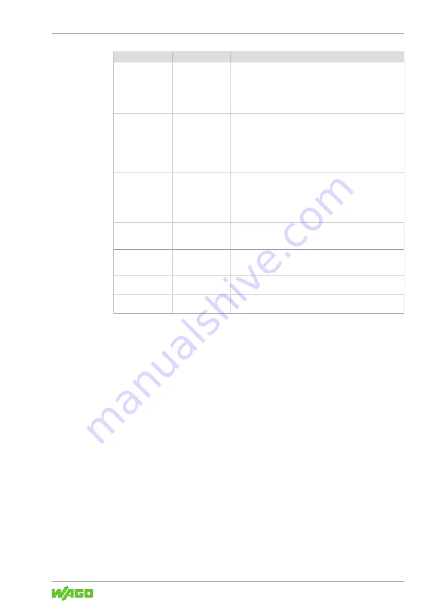
Connection
Name
Description
Connection 6
Exclusive Owner –
16 bytes per IO-Link
port without config
•
No port parameters are transferred to the module through this
connection.
•
The scanner can read the module’s input data and write the
output data.
•
IO-Link devices with up to 16 IO-Link input and output data
points each can be used.
Connection 7
Listen Only –
16 bytes per IO-Link
port
•
No port parameters are transferred to the module through this
connection.
•
The scanner can read the module’s input data.
•
An additional scanner that communicates with module via an
“Exclusive Owner” connection is necessary.
•
IO-Link devices with up to 16 IO-Link input and output data
points each can be used.
Connection 8
Input Only – 16
bytes per IO-Link
port
•
The port parameters are set with the configuration software of
the scanner and transferred to the module through this con-
nection.
•
The scanner can read the module’s input data.
•
IO-Link devices with up to 16 IO-Link input and output data
points each can be used.
Connection 9
Exclusive Owner –
4 bytes per IO-Link
port
Like connection 5, but IO-Link devices with at most 4 IO-Link input
and output data points.
Connection 10
Exclusive Owner –
4 bytes per IO-Link
port without config
Like connection 6, but IO-Link devices with at most 4 IO-Link input
and output data points.
Connection 11
Listen Only – 4 bytes
per IO-Link port
Like connection 7, but IO-Link devices with at most 4 IO-Link input
and output data points.
Connection 12
Input Only – 4 bytes
per IO-Link port
Like connection 8, but IO-Link devices with at most 4 IO-Link input
and output data points.
10.2.1.3 Setting Parameters
Set the module and port parameters in the configuration software of the EtherNet/IP
scanner to define the behavior of the module and the required port functions for use of
the connected sensors and actuators.
You can find all the module parameters under
8
.
10.3 Parameterization
The following tools are described below:
• WAGO Webserver I/O Field
•
8
• WAGO I/O Field app
• OPC UA Server
10.3.1 WAGO Webserver I/O Field
10.3.1.1 Call WAGO Webserver I/O Field
This section describes how you can use the integrated software “WAGO Webserver I/O
Field” to get access to detailed information on the current operating state of the product
and make settings to affect the product’s behavior.


