51
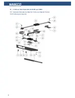
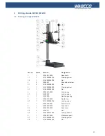
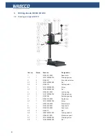
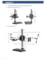
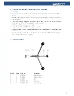
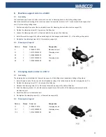
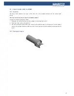
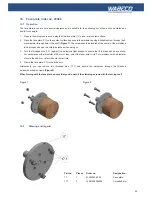
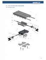
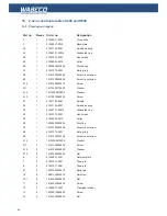
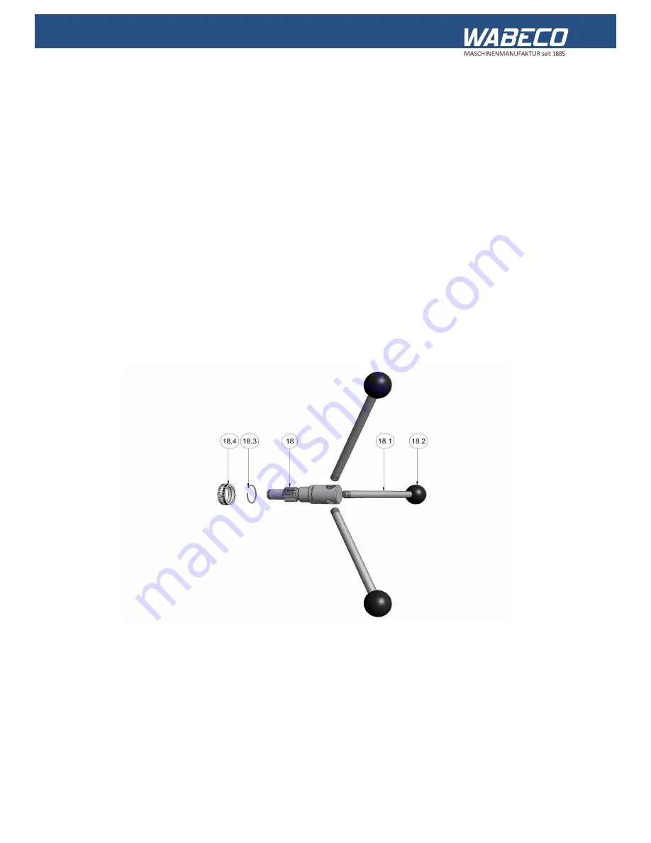
6.2 Drawing and legend
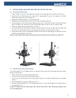
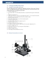
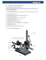
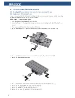
1. Screw the three feed levers for the hub (18.1) clockwise into the angled drilled holes of the feed shaft for the
hub (18).
2. Clamp the guide housing (12) onto the steel column (7) by turning the clamping screws (3) clockwise with a
6 mm Allen wrench.
3. Insert a slotted screwdriver into one of the recesses of the lock washer (8.3) and press the lock washer (8.3)
out of the groove of the feed shaft (8) by turning the slotted screwdriver.
4. Pull the feed shaft (8) out of the guide housing (12).
5. Insert the feed shaft for the hub (18) into the guide housing (12).
6. Insert the lock washer (8.3) in the groove of the feed shaft for the hub (18) and push it into position with a slotted
screwdriver.
7. Loosen the clamping screws (3) with a 6 mm Allen wrench counterclockwise until the guide housing (12) can
easily be moved on the steel column (7) again.
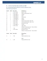
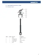
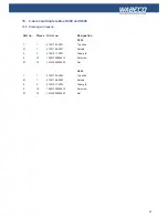
6. 3-spoke hub for Z-axis vertical travel order no. 24462
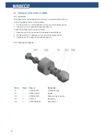
6.1 Assembly
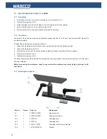
Part no.
Pieces
Order no.
Designation
18
1
51407190
Feed shaft for hub
18.1
3
51508040
Feed lever for hub
18.2
3
51508311
Ball
18.3
1
51007970-0001
Spring ring
18.4
1
51006731-00011
Graduated ring

