72
16. 2-axis coordinate tables K400 and K600
16.6 Mounting kit for mountable vernier scales for 2 axes and spindle Y-axis
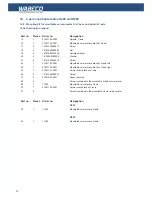
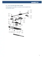
16.6.4 Mounting the mountable vernier scale X-axis to K400
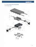
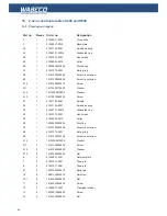
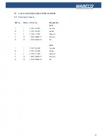
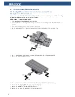
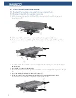
1. Hold the mountable vernier scale (23) on the two mountable vernier scale brackets left (22) and right (24)
2. The rear holes in the display of the mountable vernier scale (23) must align with the rear slots in the X-axis vernier
scale bracket (25). Shift the display adequately for this
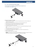
3. Use the screws (28) to screw the display of the mountable vernier scale (23) through the slots of the
X-axis (25) vernier scale bracket from below
4. Tighten the screws hand tight using a Phillips head screwdriver
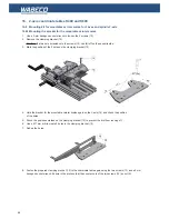
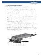
5. Align the fastening holes of the mountable vernier scale (23) with the external holes of the 2 mountable vernier
scales brackets left (22) and right (24)
6. Fit the washers (20) onto the screws (21) and insert the screws (21) into the fastening holes of the mountable vernier
scale (23).
7. Use a 3 mm hexagon socket wrench to screw the 2 screws (21) hand-tight into the external fastening threads
intended for this in the 2 mountable vernier scale brackets left (22) and right (24).
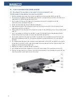
8. Use the hand crank (4.4) to move the X-axis to the 2 end positions of the mountable vernier scale (23) and then
tighten the corresponding screws (21). This process enables the mountable vernier scale (23) to be optimally
positioned.
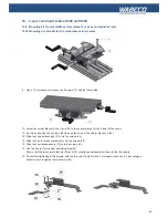
9. Any required height adjustment of the mountable vernier scale bracket on the left (22) and right (24) can be made
by loosening the screws (21) which clamp the mountable vernier scale bracket in the front T-groove using a 3 mm
hexagon socket wrench with a spherical head
10. Retighten the screws (21) following the height adjustment.
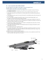
11. Use a Phillips head screwdriver to tighten the 2 screws (28) on the display of the mountable vernier scale 23)
12. Then use the hand crank (4.4) to move the Y-axis to the two end positions of the mountable vernier scale (23) and
check the mountable vernier scale for ease of movement

