


OptiFlow™ SideWings
Installation
5.6
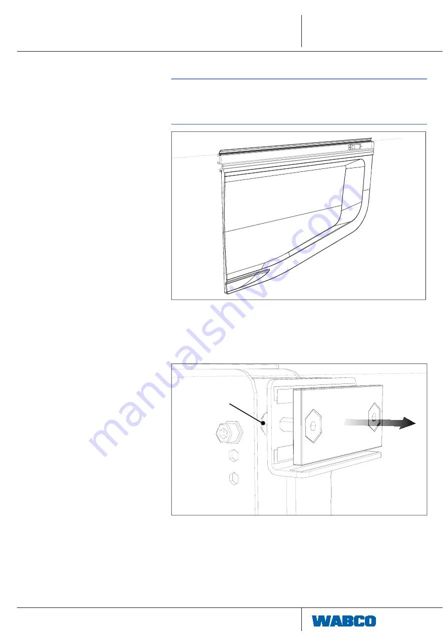
Installation of EndSkirts
!
The distance between the outer sides of the tires and the SideWings
components should not be less than 30mm.
The assembly tolerances are +/- 3mm.
–
– Install rubber on skirts before installing on trailer.
Install rubber on skirts before installing on trailer.
For OEM (Original Equipment Manufacturer) installation the top rubber may
be supplied separatel.
–
– Pull the slider thread plates of the pillars out.
Pull the slider thread plates of the pillars out.
Do not remove the nuts (see following fi gure, item A) on the back side.
Do not remove the nuts (see following fi gure, item A) on the back side.
A
Summary of Contents for OPTIFLOW SIDEWINGS
Page 1: ...OPTIFLOWTM SIDEWINGS INSTALLATION MANUAL...
Page 32: ...32 OptiFlow SideWings Installation Undo the screws on the slider Remove the slider...
Page 45: ...45 OptiFlow SideWings Operation 7 Operation 7 1 Hatches Opening Press the first knob...
Page 48: ...48 OptiFlow SideWings Operation 7 3 Hinged Pillars Pull out the safety pin...
Page 54: ...54 OptiFlow SideWings Appendix 10 2 Example of SideWings Positioning drawing...


