VW CGRA Workshop Manual Download Page 205

Pro

te

c

t

ed

  b

y

  co

p

y

rig

h

t. 

C

o

p

y

in

g

  fo

pr

iv

a

t

e

 o

r

 c

o

m

m

e

r

c

ia

p

u

rp

o

s

e

s

,

 i

n

 p

a

rt

o

r i

n

 w

h

o

le

is

 n

o

t

 p

e

r

m

it

t

e

d

 u

n

l

e

s

s

 a

ut

ho

r

i

s

ed

 b

y

 V

olk

sw

a

ge

n AG

.


V

olk

s

w

a

g

en

 AG do

es 

n

ot g

uar

ante

e

 or a

c

c

ep

t

 a

ny


li

a

b

i

li

t

y

 w

ith

 r

e

s

p

e

c

t

 t

o


th

e

 c

o

rr

e

c

t

n

e

s

s


o

f

in

fo

r

m

a

tio

n

 in

 th

is

 d

o

c

um

en

t.

C

o

py

rig

ht b

y


V

olk

sw

a

ge

n


A

G.

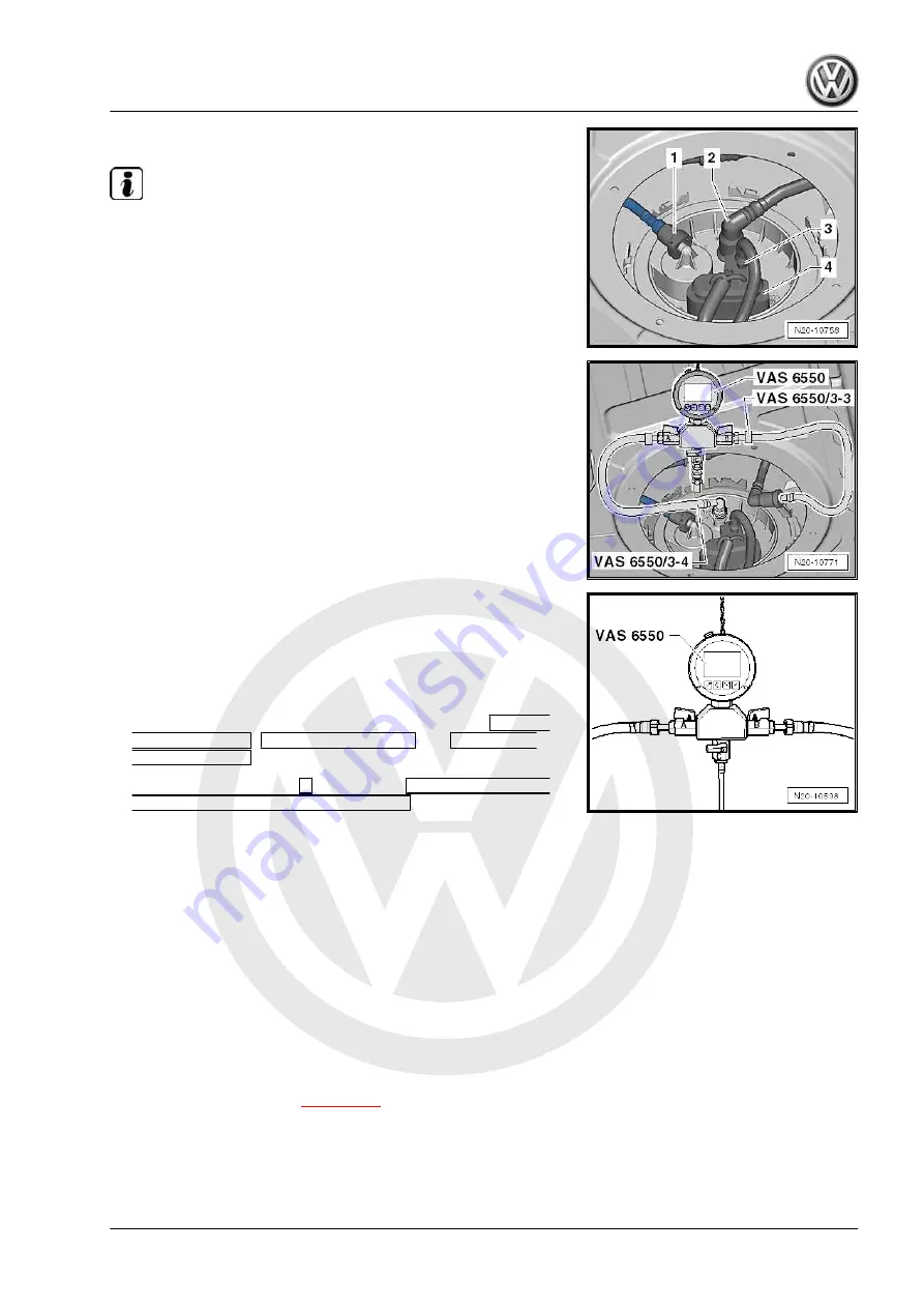
– Pull off fuel supply line -2-.

Note

Release connection by pressing button on hose coupling.

– Connect pressure tester - VAS 6550- to connecting line - VAS

6550/3-4- and connecting line - VAS 6550/3-3- as shown.

– Open shut-off taps “A” and “B” of pressure tester - VAS 6550-

and open in flow direction.

– Close shut-off tap “C”.
– Connect the vehicle diagnostic tester .
– Switch on ignition.
– Press one after the other in the display the buttons for 

Vehicle

self-diagnosis

Engine electronics

 and 

Final con-

trol diagnosis

.

– Press right arrow button 

 on display to 

Final control di-

agnosis for fuel pump electronics

.

The fuel pump must now run slowly up to maximum speed.
– Read pressure shown by pressure tester - VAS 6550- .
• Specification: 5.0 … 7.0 bar
– Switch off ignition.
If the specifications are now attained:
– Check fuel supply line from fuel tank to engine for possible

damage.

If the specifications are again not attained:
– Check all couplings and fuel lines in fuel tank and fuel delivery

unit to make sure they are firmly seated and are not leaking.

If no fault is found:
– Renew fuel delivery unit 

⇒ page 188

 .

Touareg 2010 ➤ , Touareg 2015 ➤

6-cylinder direct-injection engine (3.6 l engine, 4V) - Edition 12.2019

3. Checking fuel pump    

199

Summary of Contents for CGRA

Page 1: ...enAG VolkswagenAGdoesnot guaranteeorac c e p t a n y l i a b i l i t y w i t h r e s p e c t t o t h e c o r r e c t n e s s o f i n f o r m a t i o n i n t h i s d o c u m e n t C o p y r i g h t b y V o l k s w a g e n A G Workshop Manual Touareg 2010 Touareg 2015 6 cylinder direct injection engine 3 6 l engine 4V Engine ID CGR A CMT A Edition 12 2019 Service Service Department Technical Informa...

Page 2: ...roup 00 Technical data 10 Removing and installing engine 13 Crankshaft group 15 Cylinder head valve gear 17 Lubrication 19 Cooling 20 Fuel supply system 24 Mixture preparation injection 26 Exhaust system 28 Ignition system Technical information should always be available to the foremen and mechanics because their careful and constant adherence to the instructions is essential to ensure vehicle roa...

Page 3: ...nd installing engine 7 1 1 Removing engine 7 1 2 Separating engine and gearbox 19 1 3 Securing engine on engine support 21 1 4 Installing engine 22 1 5 Supporting engine in installation position 24 2 Assembly mountings 27 2 1 Assembly overview assembly mountings 27 2 2 Removing and installing engine mounting 27 13 Crankshaft group 29 1 Dismantling and assembling engine 29 1 1 Part I 30 1 2 Part II...

Page 4: ... camshaft 105 3 6 Camshaft identification 110 4 Inlet and exhaust valves 111 4 1 Renewing valve stem seals 111 4 2 Valve dimensions 113 4 3 Checking valve guides 113 4 4 Reworking valve seats 114 17 Lubrication 116 1 Sump oil pump 116 1 1 Assembly overview sump oil pump 116 1 2 Engine oil 118 1 3 Removing and installing oil pan 119 1 4 Removing and installing oil pump 122 2 Oil filter oil pressure...

Page 5: ...uction jet pumps 177 2 4 Removing installing and renewing fuel filter 179 2 5 Emptying fuel tank 181 2 6 Removing and installing fuel gauge sender 2 G169 and suction jet pump 184 2 7 Removing and installing fuel delivery unit and fuel gauge sender G 188 2 8 Removing and installing fuel tank with attached components 191 3 Checking fuel pump 196 3 1 Checking fuel pressure 196 3 2 Checking holding pr...

Page 6: ...p 248 7 1 Assembly overview high pressure pump 248 7 2 Removing and installing high pressure pump 249 26 Exhaust system 253 1 Exhaust manifold 253 1 1 Assembly overview exhaust manifold 253 1 2 Removing and installing exhaust manifold 253 2 Silencers and catalytic converters 256 2 1 Assembly overview catalytic converter 256 2 2 Assembly overview silencers 258 2 3 Separating centre and rear silence...

Page 7: ...2 1 1 Safety regulations for working on fuel supply Risk of injury from highly pressurised fuel The fuel system is pressurised Injury from fuel spray possible Before opening the fuel system Wear protective goggles Wear protective gloves To release pressure wrap a clean cloth around the connection and carefully loosen the connection Danger of fire caused by escaping fuel When the battery is connect...

Page 8: ...rear seat 1 4 Safety precautions when working on ignition system Risk of injury due to electric shock The ignition system is under high voltage when the engine is run ning Touching the ignition system may result in an electric shock Do not touch or disconnect ignition cables when the engine is running or being turned at starter speed Risk of damage to components Connecting or disconnecting electri...

Page 9: ... fourth digit shows the engine output and torque and varies according to engine control unit The four digit engine code can be found on the identification plate and on the vehicle data sticker It can also be read from the engine control unit Fitting locations of vehicle data sticker Maintenance Booklet Vehicle data sticker Engine data Codes CGRA CMTA Manufactured 15 2010 34 2010 Displacement cm 35...

Page 10: ...ot guaranteeorac c e p t a n y l i a b i l i t y w i t h r e s p e c t t o t h e c o r r e c t n e s s o f i n f o r m a t i o n i n t h i s d o c u m e n t C o p y r i g h t b y V o l k s w a g e n A G 2 2 Numbering of cylinders Note Cylinder 1 is opposite the power delivery side Firing order 1 5 3 6 2 4 Touareg 2010 Touareg 2015 6 cylinder direct injection engine 3 6 l engine 4V Edition 12 2019 ...

Page 11: ...mpressed air Do not move the vehicle Make sure that no fuel gets onto the fuel hoses Should this occur the fuel hoses must be cleaned immediately Protect disconnected electrical connectors from dirt and water and reconnect them only when dry 3 2 Foreign objects in engine To prevent the ingress of foreign bodies during work on the en gine seal open channels of the intake section and exhaust sec tio...

Page 12: ... n f o r m a t i o n i n t h i s d o c u m e n t C o p y r i g h t b y V o l k s w a g e n A G 3 5 Fitting radiator and condensers Even if installed correctly the radiator the condenser and the charge air cooler may have small dents in their fins This does not mean that these components have been damaged It is not per missible to renew radiators condensers or charge air coolers only because of suc...

Page 13: ... e s s o f i n f o r m a t i o n i n t h i s d o c u m e n t C o p y r i g h t b y V o l k s w a g e n A G 10 Removing and installing engine 1 Removing and installing engine 1 1 Removing engine page 7 1 2 Separating engine and gearbox page 19 1 3 Securing engine on engine support page 21 1 4 Installing engine page 22 1 5 Supporting engine in installation position page 24 1 1 Removing engine Touare...

Page 14: ...r e c t n e s s o f i n f o r m a t i o n i n t h i s d o c u m e n t C o p y r i g h t b y V o l k s w a g e n A G Special tools and workshop equipment required Lifting tackle 3033 Engine and gearbox support VAS 6095 Engine and gearbox jack V A G 1383 A Drip tray V A G 1306 Workshop hoist VAS 6100 Scissor type assembly platform VAS 6131 Pliers for spring type clips VAS 6340 Touareg 2010 Touareg 2...

Page 15: ...e suitable materials e g cable ties to attach all disconnec ted cables and wires to the engine assembly depending on origin Fit dummy plugs in all open connections Move the selector lever to the N position so that the propshaft can turn freely To make sure you can still move the front wheels when the battery has been disconnected only disconnect the battery with the ignition key inserted Procedure...

Page 16: ...system Detach all connectors whose wires go to the engine Remove engine wiring harness from plenum chamber and place it on the engine Disconnect connectors 1 to 4 for lambda probes WARNING The fuel line is under pressure Fuel poses danger of injury to eyes and skin Wear protective goggles and protective clothing to avoid injury and contact with the skin Wrap a cloth around the connection before lo...

Page 17: ...s arrows Hose 1 can be disregar ded Open cover above terminal B distribution box arrow Unscrew and disconnect positive wire 1 To alternator 2 To starter Move electrical wiring clear Siphon off refrigerant of the air conditioning system Rep gr 87 Detach power assisted steering hose together with clamps up to 25 mm 3094 Pull hose A off power steering pump Detach refrigerant lines 2 and 3 from air co...

Page 18: ...C o p y r i g h t b y V o l k s w a g e n A G Unbolt bracket for noise insulation arrows Drain coolant page 154 Open plug in connector A under the coolant expansion tank and pull off coolant hose Unscrew connection of coolant hose at top of radiator Open plug in connector A at top of radiator and pull coolant hose off Detach coolant hose from lower radiator connection Remove front wheels Unscrew e...

Page 19: ... p y r i g h t b y V o l k s w a g e n A G Unscrew bolt A and pull connections off gear oil cooler Catch oil which runs out Disconnect hose of servo steering with hose clips up to 25 mm 3094 open clip A and pull off hose Open clips A and pull off coolant hoses of heat exchanger for heating system Push propshaft off gearbox and tie at the top Differential and final drive Rep gr 39 Removing and inst...

Page 20: ...rs 1 and 2 Loosen clamps arrows and push to rear Separate selector lever cable at ball head 1 and unscrew from gearbox 2 Circlip 3 can remain fitted Caution Danger of airbag coil connectors becoming twisted Only disconnect universal joint from steering rack when front wheels are in straight ahead position Secure steering wheel with adhesive tape so that position of steering wheel and steering rack...

Page 21: ...ight from front speed sen sors arrow Disconnect connector arrow for wear indicator Remove bolts arrows for cable retainers Unscrew bolts 1 for brake caliper Note Do not attempt to bend brake lines to a different shape Suspend brake caliper in wheel housing with wire Caution Avoid damage to brake pistons Do not press brake pedal when brake caliper is removed Unscrew nut for suspension link at top b...

Page 22: ...ve bolt in hole Repeat work sequence of suspension on opposite side of ve hicle Unscrew one of the rear securing bolts 2 on subframe Secure subframe to body using locating pins T10300 Running gear axles steering Rep gr 40 l Assembly over view subframe anti roll bar lower suspension links Then proceed with other securing bolt 2 in the same way If the engine and gearbox are to be separated after bei...

Page 23: ...AS 6131 6 5 Bolting point B7 6 VAS 6131 6 5 Bolting point G7 7 VAS 6131 6 6 Bolting point B14 8 VAS 6131 6 6 Bolting point G14 Note All supports must only be tighten by hand so that their position can still be adjusted The basic set for Touareg VAS 6131 6 consists of the sup ports VAS 6131 6 1 to VAS 6131 6 7 To make the fol lowing procedure easier to understand we designate them here as support 1...

Page 24: ...nto corresponding mountings on left and right arrow At the same time guide the supports 6 for the left and right sides of the gearbox transverse into corresponding holes arrows When all four supports are in the receptacle holes without pres sure Guide supports 5 into their respective receptacles in sub frame If necessary adjust support height with knurled nut Screw all supports to scissor lift tab...

Page 25: ...rame 3 and 4 Caution Be very careful when lowering Make sure that all connections to the body have been detached Do this now if necessary Now slowly lower engine gearbox assembly constantly ob serving the clearance On left and right sides tighten one securing bolt with nut arrow from subframe mounting This prevents the engine carrier from slipping 1 2 Separating engine and gearbox Unscrew or detac...

Page 26: ...d gearbox use wooden wedges for example to prevent engine from tipping over When separating the engine and gearbox press off torque converter from drive plate through opening of removed starter motor Unscrew and remove all engine gearbox connecting bolts Loosen clamping bolts 1 on side of scissor type assembly platform VAS 6131 A and pull rear section of platform to gether with gearbox towards rea...

Page 27: ...ort VAS 6095 to carry out repairs Secure engine on engine bracket 3269 in order to do work on chain drive Special tools and workshop equipment required Engine and gearbox support VAS 6095 or engine support 3269 Procedure Separate engine and gearbox page 19 Secure torque converter against falling out after separating engine from gearbox Attach lifting tackle 3033 as follows and lift engine from sci...

Page 28: ...1 4 Installing engine Caution Observe the following during all assembly work particularly in the engine compartment due to the restricted space Route lines of any kind and cables so that original routing is restored Ensure that there is sufficient clearance to all moving or hot components Note When fitting engine and gearbox to body it is essential to position engine carrier against body with the ...

Page 29: ...propriate securing points of subframe Switch on dot lasers and align scissor type assembly platform so that the laser beams on left and right strike the bolt heads After completing alignment remove dot lasers and adapters Installing engine Raise engine until it contacts the body using scissor type as sembly platform VAS 6131 Observe the inserted locating pins T10300 in the process Bolt subframe to...

Page 30: ...automatically Generate readiness code in connection with test drive Observe applicable safety measures when carrying out a road test Then carry out vehicle system test again and rectify any faults which may have occurred Note Check wheel alignment if during the road test it is determined that the steering wheel is not in the straight ahead position when mov ing straight ahead Running gear axles st...

Page 31: ... g e n A G Special tools and workshop equipment required Support bracket 10 222 A with adapters 10 222 A 29 2 x hooks 10 222 A 10 Adapter 10 222 A 28 Square section tube T40091 1 qty 2 Hook rail T40091 2 2 x articulated joints T40091 3 Support bearing T40093 5 2 x articulated joints T40093 4 Slide rotary joints T40091 3 and hooks 10 222 A 10 onto square section tube of bracing device 10 222 A Fit ...

Page 32: ...ted joint T40093 4 as well as adapter 10 222 A 28 onto square tube T40091 1 Place adapter 10 222 A 28 onto longitudinal member and push square tube T40091 1 into articulated joint T40091 3 Repeat procedure on opposite side of vehicle Push hook rail T40091 2 on one side through articulated joint T40093 4 Push mounting T40093 5 onto the hook rail T40091 2 then slide hook rail onto other side of rota...

Page 33: ...1 Assembly overview assembly mountings page 27 2 2 Removing and installing engine mounting page 27 2 1 Assembly overview assembly mountings 1 Engine carrier bolts 120 Nm turn 180 fur ther Renew 2 Right engine mounting 3 60 Nm 4 40 Nm 5 Cable bracket 6 75 Nm 7 Right engine support 8 Left engine support With oil filter housing 9 25 Nm 10 Cable bracket 11 Cable bracket 12 25 Nm 13 60 Nm 14 Left engin...

Page 34: ...s o f i n f o r m a t i o n i n t h i s d o c u m e n t C o p y r i g h t b y V o l k s w a g e n A G Unscrew nuts for engine mounting on left and right sides arrow Lift engine evenly with both spindles until threaded engine mounting stud is free Remove securing bolts for engine mounting Remove engine mounting Installing Assemble in reverse order of dismantling Specified torques page 27 Touareg 20...

Page 35: ...r e s p e c t t o t h e c o r r e c t n e s s o f i n f o r m a t i o n i n t h i s d o c u m e n t C o p y r i g h t b y V o l k s w a g e n A G 13 Crankshaft group 1 Dismantling and assembling engine Overview 1 1 Part I page 30 1 2 Part II page 32 1 3 Removing and installing poly V belt page 34 1 4 Removing and installing vibration damper page 35 Touareg 2010 Touareg 2015 6 cylinder direct injec...

Page 36: ...urther damage perform the following repairs Thoroughly clean oil channels Renew oil spray jets Renew engine oil cooler Renewing oil filter 1 1 Part I 1 Valve timing housing Lightly lubricate contact surface of oil seals be fore installing Removing and installing page 105 Removing and installing cam shafts Assembly overview page 102 Before installing valve timing housing check strainer for soiling ...

Page 37: ...using 27 mm open end spanner on camshaft page 105 Removing and installing camshafts 14 Inlet camshaft adjuster Identification 24E Install camshaft adjuster with camshaft timing chain page 64 15 10 Nm 16 Chain tensioner with tensioning rail For timing chain Item 19 page 31 Only rotate engine when chain tensioner is installed 17 Drive gear Built into crankshaft Ground down tooth aligned with main be...

Page 38: ...rection of rotation Note Do not mark chain by way of centre punch notch or the like 1 2 Part II 1 Vibration damper securing bolts Qty 7 60 Nm turn 180 fur ther 2 Vibration damper Removing and installing page 35 Removing and installing poly V belt page 34 3 Guide tube for oil dipstick Secured with bolt to in take manifold 4 Cylinder block Sealing flanges and fly wheel or drive plate page 36 Cranksh...

Page 39: ...m Insert with locking fluid D 000 600 A2 16 Oil pressure pipe 17 8 Nm Insert with locking fluid D 000 600 A2 18 Oil drain plug 30 Nm With captive seal Renew 19 Sump Removing and installing page 119 20 Oil level and oil temperature sender G266 21 12 Nm 22 Securing bolt for oil sump 10 Nm 23 Oil filter housing left engine bracket Dismantling and assembling page 128 Connection diagram for coolant hos...

Page 40: ...sioning arm in direction of arrow using a suitable screwdriver Screw M8 50 bolt into threaded hole A and secure poly V belt tensioning roller Note Screw in bolt only far enough to remove poly V belt as tensioning roller housing may otherwise be damaged Remove poly V belt Installing poly V belt Note Ensure before installing poly V belt that all ancillaries alter nator air conditioner compressor van...

Page 41: ...2A Screw in bolts T10172A 1 Removing Remove poly V belt page 34 Remove radiator cowl page 170 Lock vibration damper using counterhold T10172A and adapter T10172A 1 Unscrew securing bolts and remove vibration damper from crankshaft journal Installing Note Check rubber joint between inner and outer ring of vibration damper for cracks and separation If rubber joint is damaged re new vibration damper ...

Page 42: ... Assembly overview sealing flanges and drive plate page 36 2 2 Assembly overview timing chain covers page 37 2 3 Removing and installing seal on gearbox side page 38 2 4 Removing and installing sealing flange on gearbox side page 40 2 5 Renewing crankshaft sealing flange vibration damper side page 43 2 6 Removing and installing drive plate page 45 2 7 Removing and installing bracket for ancillarie...

Page 43: ...With seal Renewing page 43 5 Cylinder block Assembly overview crankshaft page 49 Assembly overview pistons and conrods page 56 6 Sealing flange Removing and installing page 40 7 Seal Remove using extractor hook T20143 2 Do not oil or grease the oil seal sealing lip Before installing re move oil residue from crankshaft journal using a clean cloth Installing page 38 8 Shim 9 60 Nm turn 90 further Re...

Page 44: ...ox side Removing and installing page 40 3 Bolt 23 Nm 4 Bolt Tighten in stages and in diagonal sequence 8 Nm 5 Seal Qty 2 For camshaft control valve 1 N205 and ex haust camshaft control valve 1 N318 Renew if leaking or damaged Renewing page 94 6 Bolt 8 Nm 7 Hall sender Hall sender G40 and Hall sender 2 G163 8 O ring Qty 2 Renew 9 Dowel pins Qty 2 10 Cover for timing chain 11 Cylinder head gasket Cl...

Page 45: ... m a t i o n i n t h i s d o c u m e n t C o p y r i g h t b y V o l k s w a g e n A G Fitting tool T10122 Extractor hook T20143 Remove seal Proceed as follows Remove gearbox Automatic gearbox 0C8 8 speed Rep gr 37 Remove drive plate page 45 Fit puller hooks T20143 2 behind sealing lip of oil seal as shown in illustration Support puller hook T20143 2 on sealing flange and lever seal out in directi...

Page 46: ...parate the two fitting sleeves Then set pulling sleeve T10122 2 with dry oil seal onto crankshaft journal Tap sealing ring into sealing flange as far as it will go using the thrust piece T10122 3 to do so Further assembly is basically a reverse of the dismantling se quence 2 4 Removing and installing sealing flange on gearbox side Special tools and workshop equipment required Hand drill with plast...

Page 47: ...ess crankshaft oil seal out of lower timing chain cover Installing Specified torques page 37 Caution The lubrication system can be soiled by sealant residue Care fully cover open parts of engine so that no sealant residue can fall into it Remove remaining sealant from sealing flange and from cyl inder block e g using a rotating plastic brush Wear protective goggles Clean sealing surfaces they must...

Page 48: ...d cylinder head Clean top and bottom of cylinder head gasket both faces must be free of oil and grease Cut off nozzle on tube at front marking of nozzle approx 2 mm Apply thin coating of sealant to upper and lower sealing sur faces of cylinder head gaskets to do this bend cylinder head gasket downwards very slightly arrows To coat the surface between cylinder head and gasket use a flat object e g ...

Page 49: ...hown and install Note The sealing flange must be installed within 5 minutes after sealant application Tighten bolts in 3 stages as follows A Pre tighten bolts 1 to 5 Nm B Tighten bolts 2 to 23 Nm C Tighten bolts 1 to 10 Nm Continue installation in the reverse order of removal observing the following Install crankshaft oil seal page 38 Install sump page 119 Install drive plate page 45 Install engin...

Page 50: ... h t b y V o l k s w a g e n A G Torque wrench V A G 1332 Counter hold tool T10172 with adapter T10172 1 Cleaning solution D 291 091 A1 Sealant D 176 501 A1 Removing Remove poly V belt page 34 Remove vibration damper page 35 Unscrew bolts 1 and 2 Carefully prise off sealing flange Remove sealant residue from sealing surfaces Installing Clean sealing surfaces with cleaning solution D 291 091 A1 Thi...

Page 51: ...ng ring with a clean cloth The sealing compound bead must not be thicker than 2 to 3 mm Otherwise excessive sealing compound will enter the sump and may block the oil suction pipe strainer Observe use by date of sealant The sealing flange must be installed within 5 minutes after ap plying the silicone sealant Slide sealing flange 1 over guide sleeve 2 provided and carefully onto crankshaft journal...

Page 52: ... w a g e n A G Counter hold tool T10172 with adapter T10172 1 Torque wrench V A G 1332 Removing Proceed as follows Remove gearbox Automatic gearbox 0C8 8 speed Rep gr 37 Lock vibration damper using counterhold T10172 Loosen drive plate securing bolts diagonally and remove Remove drive plate Installing Fit drive plate on crankshaft Insert at least 3 old securing bolts and tighten to 30 Nm Measure d...

Page 53: ...ate again and fit appropriate shim 1 Note Only one shim of the appropriate thickness may be used for com pensation When specification is attained Insert new securing bolts and tighten by hand Tighten securing bolt to 60 Nm turn 90 further 2 7 Removing and installing bracket for an cillaries Removing Proceed as follows Remove poly V belt page 34 Remove alternator Rep gr 27 Remove power assisted ste...

Page 54: ... o n i n t h i s d o c u m e n t C o p y r i g h t b y V o l k s w a g e n A G Installing Install in reverse order of removal observing the following Tighten bolts in sequence 1 to 5 in 2 stages as follows 1 Tighten bolts by hand 2 Tighten bolts to 25 Nm Note Bolts 1 and 2 are fitted bolts Install A C compressor Rep gr 87 Install power assisted steering pump Rep gr 48 Install alternator Rep gr 27 ...

Page 55: ...ace for storing crankshaft to ensure that sender wheel Item 6 page 50 is not damaged or lies against any other item Secure engine on engine and gearbox support VAS 6095 to carry out repairs 3 1 Assembly overview crankshaft 1 Bearing cap Bearing cap 1 vibration damper end Bearing cap 5 with re cesses for thrust wash ers Bearing shell retaining lugs in cylinder block and bearing caps must align 2 30...

Page 56: ...her Renew 8 Oil spray jet For crankshaft bearings 2 to 7 For piston cooling Opening pressure 2 0 bar Removing and installing page 128 3 2 Fitting sender wheel to crankshaft Special tools and workshop equipment required Torque wrench V A G 1331 Locking fluid D 154 100 A1 Procedure Ensure that contact surfaces of crankshaft and sender wheel are free of oil and grease Note The sender wheel must only ...

Page 57: ...ain bearing shells are allocated according to manufacturing date Allocation of main bearing shells up to and including manu facturing date 230912 page 51 Allocation of main bearing shells from manufacturing date 240912 page 53 3 3 1 Allocation of main bearing shells up to and including manufacturing date 23 09 12 Note It is essential to observe the manufacturing date The manufac turing date is emb...

Page 58: ...for the allocation of the bearing shells are located on the outer crankshaft web of No 1 cylinder Note letters and identify colour code to be installed based on table Letter on cylinder block Letter on crankshaft web Colour marking of bearing shell for cylinder block up per bearing shell Colour marking of bearing shell for bearing cap low er bearing shell A B C R red red A B C G yellow red A B C B...

Page 59: ...ellow yellow 3 3 2 Allocation of main bearing shells from manufacturing date 24 09 12 Note It is essential to observe the manufacturing date The manufac turing date is embossed on the crankshaft web Establish manu facturing date page 51 Main bearing shells of the correct thickness are allocated to the cylinder block and crankshaft at the factory Coloured dots are used to identify the thickness of ...

Page 60: ... block Letter on crankshaft web Colour marking of bearing shell for cylinder block up per bearing shell Colour marking of bearing shell for bearing cap low er bearing shell A B C F red red A B C E yellow red A B C D yellow yellow A B C C blue yellow A B C B blue blue A B C A violet blue D E G F yellow red D E G E yellow yellow D E G D blue yellow D E G C blue blue D E G B violet blue D E G A viole...

Page 61: ... t n e s s o f i n f o r m a t i o n i n t h i s d o c u m e n t C o p y r i g h t b y V o l k s w a g e n A G Crankshaft bearing 1 2 3 4 5 6 7 Letters on crankshaft web A B A C C A B Colour marking of bearing shell for cylinder block upper bearing shell violet violet violet blue blue violet violet Colour marking of bearing shell for bearing cap lower bearing shell violet blue violet blue blue vio...

Page 62: ...e page 57 2 Piston Checking page 58 Mark cylinder number and installation position relative to conrod The two deep valve pockets in the piston crown point to the centre of the cylinder block Installing piston page 58 3 Retaining ring Ensure firm seating 4 Connecting rod Renew as set only Mark cylinder number B Installation position marks A must be above one another 5 Bearing shell Observe installa...

Page 63: ...ap page 57 Checking ring to groove clearance page 57 Checking piston page 58 Checking cylinder bore page 58 Installing piston page 58 Piston and cylinder dimensions page 61 4 2 1 Checking piston ring gap Special tools and workshop equipment required Feeler gauge Test sequence Push ring at right angles to cylinder wall from above down to approx 15 mm from bottom end of cylinder Push in using a pist...

Page 64: ...Measure pistons approx 15 mm from the lower edge of skirt at 90 to the piston pin axis Deviation from nominal dimension max 0 06 mm 4 2 4 Checking cylinder bores Special tools and workshop equipment required Cylinder gauge VAS 6078 Test sequence Take measurements at 3 positions in both lateral direction A and longitudinal direction B Deviation from nominal dimension max 0 08 mm Note The cylinder b...

Page 65: ... s w a g e n A G Note To fit the pistons the piston fitting tool T10333 with inserted piston is positioned on the cylinder block so that the straight edge of the higher side of the piston fitting tool arrow points to the middle of the cylinder block Procedure Pull dowel sleeve arrow out of its hole before installing piston The pistons for cylinders 1 3 and 5 must be installed so that the deep valv...

Page 66: ... 2 point to the middle of the cylinder block and the arrows 3 to the vibration damper Push the correct piston for the correct cylinder into piston fitting tool until the shorter side of the piston arrow emerges approx 15 mm from lower edge of piston fitting tool Now place piston with piston fitting tool in respective cylinder bore The higher side of the piston fitting tool arrow must face middle o...

Page 67: ...t guaranteeorac c e p t a n y l i a b i l i t y w i t h r e s p e c t t o t h e c o r r e c t n e s s o f i n f o r m a t i o n i n t h i s d o c u m e n t C o p y r i g h t b y V o l k s w a g e n A G 4 3 Piston and cylinder dimensions Honing dimen sion Piston Cylinder bore Basic dimension mm 88 945 89 010 Touareg 2010 Touareg 2015 6 cylinder direct injection engine 3 6 l engine 4V Edition 12 201...

Page 68: ...ling camshaft adjuster page 64 1 3 Removing and installing camshaft timing chain page 71 1 4 Removing and installing oil pump drive timing chain page 74 1 5 Removing and installing chain drive sprocket for high pressure pump page 78 1 1 Checking valve timing Special tools and workshop equipment required Camshaft bar T10068 A Test sequence Remove noise insulation General body repairs exterior Rep g...

Page 69: ...8 A in both shaft grooves Note The grooves of the camshafts might not be exactly vertical due to the function of camshaft adjusters Therefore move the cam shafts back and forth slightly if necessary when inserting the camshaft bar T10068 A using an open end spanner arrows Check setting marks of camshaft adjusters against marks on tim ing housing Arrows on camshaft adjusters must align with right n...

Page 70: ... a g e n A G The gap between markings of camshaft adjuster must be ex actly 16 rollers of camshaft timing chain If the markings do not align Adjust valve timing page 74 If the markings align Install cylinder head cover page 90 Install upper part of intake manifold page 236 Markings on timing housing on FSI engines A View from flywheel end B View from vibration damper end The markings on camshaft a...

Page 71: ...8 A Counterhold T10172 with pins T10172 1 Torque wrench V A G 1331 Torque wrench V A G 1332 Adjusting tool T10363 Not illustrated Sealant D 176 501 A1 Removing camshaft adjuster Remove upper part of intake manifold page 236 Remove wiper arms Electrical system Rep gr 92 Wind screen wiper system Removing and installing wiper arms Removing plenum chamber cover General body repairs exterior Rep gr 64 ...

Page 72: ... V o l k s w a g e n A G Unclip wiring harness 1 undo bolt 2 and 3 remove engine lifting eye Separate the following connectors 1 Hall sender G40 2 Inlet camshaft control valve 1 N205 3 Hall sender 2 G163 4 Exhaust camshaft control valve 1 N318 Remove mechanical vacuum pump page 93 Unscrew nut A and remove bolts arrows Remove cover securing bolts arrows and lever off cover Remove noise insulation G...

Page 73: ...e n t C o p y r i g h t b y V o l k s w a g e n A G Turn crankshaft from below using counterhold T10172 in engine direction of rotation to TDC no 1 cylinder marking Cams A of cylinder 1 must face each other Unscrew bolt for camshaft adjuster approx 1 turn at outlet end using an open ended spanner to counterhold on flat side of camshaft Unscrew bolt for camshaft adjuster approx 1 turn at inlet end ...

Page 74: ...in both shaft grooves If nec essary move the camshafts back and forth slightly with an open end spanner Secure position of high pressure pump chain drive sprocket using adjusting tool T10363 The marking A on the drive cam for high pressure pump must be on top Note If the journal for vacuum pump drive is not vertical remove cam shaft bar T10068 A Turn crankshaft further in direction of rotation unt...

Page 75: ...r T10068 A First install inlet camshaft adjuster as follows Note The camshaft adjusters are locked when at rest This pre vents the sender wheel from turning when adjusting the valve timing If the locking mechanism is not engaged locked when at rest turn the adjuster in both directions by hand until it is locked If this is not possible renew camshaft adjuster Due to a fitted key camshaft adjusters ...

Page 76: ...st lie between teeth at arrow markings 24E and 32A Connect camshaft adjuster 32A with camshaft timing chain onto exhaust camshaft Observe the following when doing this The arrow 1 on camshaft adjuster 32A must align with right notch 2 of timing housing Markings on timing housing page 64 Note It must be possible to easily position the exhaust camshaft ad juster onto the exhaust camshaft Move camsha...

Page 77: ... tightened using a 27 mm open end spanner arrow Note Camshaft bar T10068 A must be removed while this is done Note that all sprocket securing bolts must be renewed Tighten securing bolts of inlet and exhaust camshaft adjusters to 60 Nm 1 4 turn 90 further Clean sealing surfaces for rear cover Coat sealing surface with sealant D 176 501 A1 Fit cover and tighten securing bolts arrows in diagonal se ...

Page 78: ...lign with bear ing joint The marked hole arrow must be in line with the mark on the oil pump Note This position is reached only after every 4th full rotation Cams A of cylinder 1 must face each other Removing camshaft adjuster page 64 Unscrew securing bolts 1 and 2 Remove guide rail A Remove camshaft timing chain out upwards Installing Condition Crankshaft is at TDC position Chain drive sprocket f...

Page 79: ... placed on the oil pump sprocket First fit camshaft timing chain onto oil pump sprocket Marking must align with middle copper coloured chain link A Fit camshaft timing chain onto chain drive sprocket of high pressure pump Marking must align with copper coloured chain link Tighten bolt 1 for guide rail Insert inlet camshaft adjuster 24E into camshaft timing chain in such a way that the copper colou...

Page 80: ...nks no longer align with the adjust ment markings once the crankshaft has been turned Install chain tensioner for camshaft timing chain arrow Specified torque 50 Nm Remove camshaft bar T10068 A and tighten bolt of camshaft adjuster Specified torque 60 Nm 1 4 turn 90 Note Only counterhold at camshaft with 27 mm open end spanner arrow The camshaft bar T10068 A must not be fitted when camshaft adjust...

Page 81: ... f i n f o r m a t i o n i n t h i s d o c u m e n t C o p y r i g h t b y V o l k s w a g e n A G Special tools and workshop equipment required Camshaft bar T10068 A Counter hold tool T10172 Torque wrench V A G 1331 Torque wrench V A G 1332 Adjusting tool T10363 Not illustrated Sealant D 176 501 A1 Removing Conditions Engine removed Engine and gearbox separated Drive plate removed Sump removed Se...

Page 82: ...by vibration damper to adjustment markings Ground tooth of drive sprocket arrow A must align with bear ing joint The marked hole arrow B must be in line with the mark on the oil pump Note This position is reached only after every 4th full rotation If the camshaft timing chain is to be replaced remove cam shaft timing chain page 71 If the camshaft timing chain is not to be replaced mark position of...

Page 83: ...s completely and remove sprockets with timing chain from oil pump Installing Set crankshaft to TDC position Ground tooth of drive sprocket arrow must align with bearing joint Now turn oil pump shaft 1 with flat side arrow horizontal to mark 2 on oil pump First only fit the rear chain onto the large sprocket When do ing this observe the previously made markings Fit chain onto crankshaft and fit spr...

Page 84: ... chain The marking made dur ing removal must align Fit sprocket onto oil pump shaft again and tighten hand tight Install chain tensioner for camshaft timing chain arrow Install lower chain tensioner and tighten to 8 Nm arrows Remove Allan key A Tighten sprockets to 60 Nm 90 1 4 turn further To do this counterhold vibration damper using counterhold T10172 Install sealing flange page 41 Further asse...

Page 85: ... shaft 4 and remove chain drive sprocket 6 Installing Note Coat faces of chain drive sprocket and bearing shaft with lubri cating paste G 052 723 A2 Insert drive sprocket The notch arrow must be on top Coat bearing shaft with lubricating paste G 052 723 A2 and push it in The bearing shaft fits in only one position Secure position of high pressure pump chain drive sprocket using adjusting tool T103...

Page 86: ...m pump page 92 2 5 Removing and installing mechanical vacuum pump page 93 2 6 Installing cover oil seals page 94 2 7 Checking compression page 95 Note To remove cylinder head engine must first be removed page 7 If an exchange cylinder head is installed all the contact sur faces between the supporting elements roller rocker fingers and the running surfaces of the camshafts must be oiled be fore the...

Page 87: ...Nm 6 Intake manifold support 7 23 Nm 8 10 Nm 9 Union 10 Seal Renew Observe installation po sition 11 Chain tensioner 50 Nm for camshaft timing chain Only rotate engine when chain tensioner is instal led 12 Seal Renew 13 Seal For camshaft control valve 1 N205 and exhaust camshaft control valve 1 N318 Renew if damaged or leaking Installing page 94 14 Cover Can be removed and installed with engine in...

Page 88: ...coolant 25 Tensioning element for poly V belt Removing and installing poly V belt page 34 26 Cylinder head bolt Renew Coat bolt with locking fluid D 197 300 A2 before installing page 89 Refer to assembly instructions and sequence when loosening and tightening page 82 Removing and installing cylinder head 27 Gasket for cylinder head cover Renew if damaged or leaking Observe installation position Ch...

Page 89: ... i o n i n t h i s d o c u m e n t C o p y r i g h t b y V o l k s w a g e n A G Special tools and workshop equipment required Camshaft bar T10068 A Drip tray for workshop hoist VAS 6208 Workshop hoist VAS 6100 Lifting tackle 3033 Pliers for spring type clips VAS 6499 Puller T10095 A Not illustrated Torque wrench V A G 1331 Torque wrench V A G 1332 Sealant D 176 501 A1 Locking fluid D 197 300 A2 C...

Page 90: ...sition during installa tion Some components cannot be removed or removed only with difficulty with the engine installed Therefore you should de termine all defective components before removing engine and renew them while engine is removed To prevent damage to removed components place them in the container for removed parts V A G 1698 Remove upper part of intake manifold page 236 Remove high pressu...

Page 91: ... o f i n f o r m a t i o n i n t h i s d o c u m e n t C o p y r i g h t b y V o l k s w a g e n A G Turn crankshaft in engine direction of rotation to TDC marking arrow using counterhold T10172 Cams A of cylinder 1 must face each other Remove vacuum pump page 93 Undo the two bolts 1 from sealing flange and then undo and remove all bolts arrows from the cover Remove chain tensioner for camshaft ti...

Page 92: ...r T10068 A must not be fitted when camshaft adjuster is loosened or tightened Unscrew securing bolts 1 and 2 and then unscrew guide rail 3 Note The camshaft timing chain is held on the sprocket of the oil pump by the bottom timing chain cover The timing chain cannot jump over Remove camshaft adjusters from camshafts Remove camshaft timing chain from sprocket for high pres sure pump Unscrew four se...

Page 93: ...fting tackle 3033 face the flywheel end Adjust length of threaded spindles according to need Carefully remove cylinder head Place clean cloths in cylinders so that no dirt or emery cloth particles can get in between cylinder wall and piston Also prevent dirt and emery cloth particles from getting into coolant Now carefully clean sealing surfaces of cylinder head and cyl inder block When doing this...

Page 94: ...176 501 A1 onto joint between cylinder block and sealing flange as shown arrows Note Do not remove new cylinder head gasket from its packing until immediately before installing Handle new gasket with extreme care Damage will cause leakage Immediately fit new cylinder head gasket Inscription Part No must be readable Additionally insert a little sealant D 176 501 A1 into the two 3 mm holes which lie...

Page 95: ...r sealing the cylinder head bolt The longer cylinder head bolts must be inserted in the centre holes of cylinder head Tighten cylinder head bolts in tightening sequence shown working from inside to outside 1 Pre tighten all bolts to 15 Nm 2 Then tighten all bolts to 30 Nm 3 Use fixed wrench to turn 90 further 4 Use fixed wrench to turn 90 further Oil sealing rings of camshafts and install valve ti...

Page 96: ...ly onto sprocket of high pressure pump and then bolt on the guide rail arrow Further assembly is basically a reverse of the dismantling se quence Install camshaft adjuster with camshaft timing chain page 69 Install cylinder head cover and intake manifold page 236 Note It is not necessary to retighten cylinder head bolts after repairs 2 3 Removing and installing cylinder head cover Special tools an...

Page 97: ... a g e n A G Removing Remove ignition coils with output stages page 272 Remove upper part of intake manifold page 236 Note Seal intake ports in intake manifold and in cylinder head with a clean cloth Unscrew securing bolts 1 and 2 and remove bracket A Expose electric cables at rear of cylinder head and unscrew cable retainer A from cover Pull off crankcase breather hose from cylinder head cover Lo...

Page 98: ...equally from inside out 1 to 17 Perform further installation in reverse order paying attention to the following Note Renew cylinder head cover if damaged or leaking Bolt intake manifold first to cylinder head Then tighten the two bolts of intake manifold support Ensure fuel hoses are seated correctly If necessary fill with coolant page 158 Specified torques Bolted connection Specified torque Cylin...

Page 99: ...i s d o c u m e n t C o p y r i g h t b y V o l k s w a g e n A G 1 Bearing shaft The splines fit in only one position into the drive sprocket 2 Cover Can be renewed with engine removed 3 Securing bolt Short 8 Nm 4 Securing bolts Long 8 Nm 5 Vacuum pump Removing and installing page 93 6 Seal Renew 7 Seal Part of vacuum pump 2 5 Removing and installing mechanical vacuum pump Removing Place wiring t...

Page 100: ...line A Remove securing bolts arrows Carefully pull vacuum pump from cylinder head Installing Check sealing ring in vacuum pump A for damage If the seal is damaged the vacuum pump must be renewed Turn rotor in vacuum pump so that the flat sides of input shaft fit into rotor Push vacuum pump evenly into fitting hole of cover to stop Tighten securing bolts arrows and reconnect vacuum line A Specified...

Page 101: ... r e s p e c t t o t h e c o r r e c t n e s s o f i n f o r m a t i o n i n t h i s d o c u m e n t C o p y r i g h t b y V o l k s w a g e n A G Fitting sleeve 3253 6 from assembly tool 3253 Installing Do not lubricate seals Install seal with fitting sleeve 3378 in cover 1 and pull in flush using fitting sleeve 3253 6 from assembly tool 3253 2 7 Checking compression Touareg 2010 Touareg 2015 6 c...

Page 102: ...ket 3122 B Puller T10095 A Assembly tool T10118 Torque wrench V A G 1331 Compression tester V A G 1763 Check condition Engine oil temperature at least 30 C Battery voltage must be at least 11 5 V All electrical consumers e g lights and rear window heating must be switched off If the vehicle is equipped with an air conditioner it must be switched off On vehicles with automatic gearbox the selector ...

Page 103: ...n puller T10095 A on from flat side of connector in direction of arrow and pull out ignition coil with output stage Unscrew spark plugs using spark plug socket and extension 3122 B Check compression using compression tester V A G 1763 adapter V A G 1381 1 and adapter V A G 1381 5A Note Using compression tester operating instructions Have a second mechanic operate starter until tester shows no furt...

Page 104: ...nto respective spark plug hole so that the flat sides of connectors fit with each other arrows After the test has been completed Connect vehicle diagnostic tester Carry out vehicle system test using Vehicle diagnostic test er End the vehicle system test so that any entries stored in the event memory during assembly can be deleted automatically Generate the readiness code in combination with a road...

Page 105: ...haft Check radial clearance with Plastigage wear limit 0 1 mm Runout max 0 01 mm Checking axial clear ance page 101 Identification page 110 Removing and installing page 105 2 Camshaft bearing caps Installation position page 108 Installation sequence page 105 Removing and installing camshaft 3 Exhaust camshaft Check radial clearance with Plastigage wear limit 0 1 mm Runout max 0 01 mm Checking axia...

Page 106: ...surface of sender wheel must be dry around bolt head when installed To remove and install counterhold using 27 mm open end spanner on camshaft page 105 Removing and installing camshafts 11 Cylinder head height Minimum height a 139 9 mm 12 Drive sprocket for high pressure pump With inner splines Bearing shaft fits in only one position 13 Bearing shaft Bearing shaft fits in only one position into ch...

Page 107: ...ft axial clearance page 101 Do not interchange Check roller bearing for ease of movement Oil contact surface When installing secure to supporting element using securing clip 23 Valve springs Observe installation position Removing and installing page 111 Renewing valve stem seals 24 Valve spring plate 25 Valve cotters 3 2 Camshafts checking axial clearance Special tools and workshop equipment requi...

Page 108: ... t b y V o l k s w a g e n A G 3 3 Assembly overview timing housing 1 Seal Renew 2 Guide rail is clipped into valve timing housing 3 Valve timing housing 4 Inlet camshaft control valve 1 N205 Removing and installing page 103 5 Bolt 3 8 Nm 6 Exhaust camshaft control valve 1 N318 Removing and installing page 103 7 8 Nm turn 180 further Renew Checking valve timing housing strainer for soiling Unclip ...

Page 109: ...r m a t i o n i n t h i s d o c u m e n t C o p y r i g h t b y V o l k s w a g e n A G 3 4 Removing and installing camshaft control valves Special tools and workshop equipment required Torque wrench V A G 1783 TORX bit set V A G 1766 Ratchet insert 1 4 VAS 6234 Socket wrench T10072 Not illustrated Sealant D 176 501 A1 Sealant D 454 300 A2 Removing Remove upper part of intake manifold page 236 Rem...

Page 110: ... nent to which it belongs Disconnect connectors from the following components of cov er Inlet camshaft control valve 1 N205 Exhaust camshaft control valve 1 N318 Hall sender G40 Hall sender 2 G163 Move wiring harness clear Unscrew nut A and remove bolts arrows Remove vacuum pump page 93 Remove cover securing bolts arrows and lever off cover Caution Cover lower chain housing carefully so that no pa...

Page 111: ...g must be free of dirt and soiling Ensure the camshaft control valves are protected from knocks and impacts Only unpack the new camshaft control valves immediately prior to installation The camshaft control valves must not be pulled into their seat with the securing bolts Only insertion by hand is per mitted Moisten seal with clean engine oil Carefully insert camshaft control valve into housing an...

Page 112: ... e c t n e s s o f i n f o r m a t i o n i n t h i s d o c u m e n t C o p y r i g h t b y V o l k s w a g e n A G Special tools and workshop equipment required Torque wrench V A G 1331 Torque wrench V A G 1332 Camshaft bar T10068 A Adjusting tool T10363 Counterhold T10172 with pins T10172 1 Not illustrated Sealant D 176 501 A1 Removing Removing the two camshaft adjusters page 64 Touareg 2010 Toua...

Page 113: ...mshaft First remove bearing caps 1 and 13 Remove bearing caps 3 and 11 Remove bearing cap 7 Loosen bearing caps 5 and 9 alternately and diagonally B Exhaust camshaft First remove bearing caps 2 and 14 Remove bearing caps 4 and 12 Remove bearing cap 8 Loosen bearing caps 6 and 10 alternately and diagonally Continuation for both camshafts Carefully remove camshafts and lay aside on clean surface Rem...

Page 114: ...ps 7 and 8 with uni versal grease G 052 735 A2 Install supporting elements in cylinder head and fit respective roller rocker finger onto respective valve stem end or support ing element Ensure that all roller rocker fingers 1 seat properly on valve stem ends and are clipped into their respective support ele ments 2 Oil running surfaces of camshafts Carefully place each camshaft in its respective b...

Page 115: ...alternately and diagonally to 5 Nm 1 8 turn 45 further Install bearing caps 2 and 14 and tighten to 5 Nm and turn 1 8 45 further Install bearing cap 8 and tighten to 5 Nm and turn 1 8 45 further Install bearing caps 4 and 12 tighten to 5 Nm and turn 1 8 45 further Continuation for both camshafts Insert camshaft bar T10068 A in both shaft grooves Before installing check valve timing housing straine...

Page 116: ...o l k s w a g e n A G Install cover start all securing bolts arrows and tighten light ly Then tighten all securing bolts Specified torque page 80 Install vacuum pump page 93 Fitting the cylinder head cover page 90 Further assembly is basically a reverse of the dismantling se quence 3 6 Camshaft identification Identification between cam pair for cylinders 4 and 5 of respective camshaft Camshaft Ide...

Page 117: ... b y V o l k s w a g e n A G 4 Inlet and exhaust valves 4 1 Renewing valve stem seals page 111 4 2 Valve dimensions page 113 4 3 Checking valve guides page 113 4 4 Reworking valve seats page 114 4 1 Renewing valve stem seals Special tools and workshop equipment required Valve lever VW 541 1 A with press tool VW 541 6 Valve assembly device 2036 with adapter plates 2036 1 Spark plug socket 3122 B Va...

Page 118: ...nsure that roller rocker fingers and support elements are not interchanged Unscrew spark plugs using spark plug socket and extension 3122 B Set piston of respective cylinder to bottom dead centre Set up valve assembly device 2036 with adapter plates 2036 1 and adjust mounting Screw adapter T40012 1 into spark plug thread connect to compressed air line with commercially available adapter and apply ...

Page 119: ...ce it in the valve stem oil seal fitting tool 3365 and push carefully onto valve guide Install camshafts page 105 Install camshaft adjuster with camshaft timing chain page 64 4 2 Valve dimensions Valve dimensions Note Do not rework valves Only lapping in is permitted Valve dimensions for inlet valves Dimension Short inlet valve Long inlet valve a mm 33 20 33 20 b mm 5 98 5 98 c mm 102 46 136 36 α ...

Page 120: ...ts Special tools and workshop equipment required Depth gauge Valve seat refacing tool Procedure Note When repairing engines with leaking valves it is not sufficient to rework or renew valve seats and valves Particularly on high mileage engines it is necessary also to check valve guides for wear page 113 Valve seats are only to be reworked to the extent required to yield a proper surface appearance...

Page 121: ... 10 2 Measured distance minus minimum dimension max permissi ble reworking dimension Example Measured distance 10 6 mm Minimum dimension 10 2 mm Max permissible reworking dimension 0 4 mm Reworking inlet valve seat a 32 8 mm diameter b max permissible reworking dimension 2 c 0 9 to 1 5 mm d max 38 0 mm r2 radius 2 0 mm Z bottom surface of cylinder head α 45 valve seat angle β 30 upper correction a...

Page 122: ...e 116 1 2 Engine oil page 118 1 3 Removing and installing oil pan page 119 1 4 Removing and installing oil pump page 122 1 1 Assembly overview sump oil pump Note Finding metal shavings or a large quantity of small metal par ticles during engine repair could indicate that the crankshaft bearings or conrod bearings are damaged To prevent this from causing further damage perform the following repairs...

Page 123: ...e 36 Removing and installing crankshaft page 49 Pistons and conrods page 56 4 O ring Renew Lubricate before as sembling 5 Oil pump To remove oil pump en gine must be removed Removing and installing oil pump page 122 6 Sprockets For timing chain Removing and installing page 30 Install camshaft adjust er with camshaft timing chain page 64 7 60 Nm 1 4 turn 90 further Renew 8 8 Nm Install with locking...

Page 124: ...hecking Current flow diagrams Electrical fault finding and Fitting locations 20 10 Nm 21 Securing bolts for oil sump Sump cylinder block 12 Nm Sump gearbox 45 Nm 22 10 Nm 23 Oil filter housing left engine support Assembly overview oil filter housing page 128 Connection diagram for coolant hoses page 135 24 23 Nm 25 Oil pressure switch Checking page 131 26 Seal Renew Lubricate before assembling 27 ...

Page 125: ...switching engine off to allow oil to flow back into sump Special tools and workshop equipment required Oil level test tool T40178 Test sequence Loosen knurled screw arrow on setting ring Set lower edge of adjustment ring to 16 mm Push tester into dipstick tube as far as it will go setting ring then pull it out again and read off the oil level Read off the value on the lower scale Engine Setting va...

Page 126: ...i g h t b y V o l k s w a g e n A G Used oil collector and extractor VAS 6622 Bit XZN 8 T40159 Sealant D 176 501 A1 Hand drill with plastic brush Scraper Safety glasses Removing Drain engine oil Note Please observe disposal instructions Support engine in its installation position page 24 Remove subframe Running gear axles steering Rep gr 40 Removing and installing subframe Remove engine carrier Th...

Page 127: ...ical connector 2 on oil level and oil temper ature sender G266 Lay wiring harness on sump to one side Unscrew gearbox sump securing bolts arrows Loosen bolts for sump 1 diagonally and unscrew them Remove sump bolts on the gearbox side arrows using bit XZN 8 T40159 through holes in gearbox Carefully lever sump off cylinder block Remove sealant residue from cylinder block with a flat scraper Remove ...

Page 128: ...te The sealant bead must not be thicker otherwise excessive seal ant enters the sump and may block the oil suction pipe strainer Fit sump immediately and tighten all sump bolts only lightly Tighten bolts in 3 stages as follows 1 Tighten bolts securing sump 1 to cylinder block in diagonal sequence to initially 5 Nm 2 Tighten bolts securing sump to gearbox arrows to 45 Nm 3 Tighten bolts securing su...

Page 129: ...To do this counterhold vibration damper using counterhold T10172 Turn engine by vibration damper to adjustment markings Ground tooth of drive sprocket arrow A must align with bear ing joint The marked hole arrow B must be in line with the mark on the oil pump Note This position is reached only after every 4th full rotation Mark position of timing chains to sprockets of oil pump using a permanent m...

Page 130: ... b y V o l k s w a g e n A G Unscrew securing bolt for sprockets completely and remove sprockets with timing chains from oil pump Unscrew oil pump securing bolts arrows Lever oil pump out evenly at lugs arrows Installing Note Do not tilt oil pump when installing Renew O ring and securing bolt for the sprockets Insert securing bolts for oil pump with locking fluid Install oil pump coat securing bol...

Page 131: ...l k s w a g e n A G Set crankshaft to TDC position Ground tooth of drive sprocket arrow must align with bearing joint Now turn oil pump shaft 1 with flat side arrow horizontal to mark 2 on oil pump First only fit the rear chain onto the large sprocket When do ing this observe the previously made markings Fit chain onto crankshaft and fit sprocket onto oil pump shaft The marked hole arrow B must be...

Page 132: ... i o n i n t h i s d o c u m e n t C o p y r i g h t b y V o l k s w a g e n A G Carefully pull sprocket off oil pump and swing upwards a little In this position fit the camshaft timing chain The marking made during removal must align Fit sprocket onto oil pump shaft again and tighten hand tight Install lower chain tensioner and tighten to 8 Nm arrows Remove Allan key A Install chain tensioner for...

Page 133: ... t h i s d o c u m e n t C o p y r i g h t b y V o l k s w a g e n A G Recheck adjustment markings Ground tooth of drive sprocket arrow A must align with bear ing joint The marked hole arrow B must be in line with the mark on the oil pump Tighten sprockets to 60 Nm 90 1 4 turn further To do this counterhold vibration damper using counterhold T10172 Install sealing flange page 41 Further assembly i...

Page 134: ...embly overview oil filter housing page 128 2 3 Removing and installing oil filter housing engine support page 130 2 4 Removing and installing oil pressure switch F1 page 131 2 5 Checking oil pressure and oil pressure switch page 131 2 1 Removing and installing oil spray jet Special tools and workshop equipment required Drift 4 mm Drift 6 mm Note Oil spray jets are installed in crankshaft bearings ...

Page 135: ...rt 25 Nm Drain before removing With bypass valve opening pressure 2 50 bar 4 Seal Renew Lubricate before as sembling 5 Oil filter element Observe change inter vals 6 23 Nm 7 Left engine support with oil filter housing Removing and installing page 130 8 Seal Renew Lubricate before as sembling 9 Oil cooler seal Renew Lubricate before as sembling 10 Engine oil cooler Ensure clearance to adjacent comp...

Page 136: ...emoving and installing oil filter hous ing engine support Used oil collector and extractor VAS 6622 A Removing Support engine in its installation position page 24 Unbolt power assisted steering reservoir and lay it to one side Remove connector arrow for engine speed sender G28 from dipstick guide tube and disconnect it Separate electrical connector 2 on oil pressure switch F1 Unscrew nut 1 and the...

Page 137: ...g Unscrew bolts lower arrows and remove left engine support with oil filter housing Do not damage wire for engine speed sender G28 while doing so Installing Specified torque page 128 Install in reverse order of removal observing the following Note Renew the seals and gaskets Check oil level page 118 2 4 Removing and installing oil pressure switch F1 Removing Proceed as follows Separate electrical ...

Page 138: ...ools and workshop equipment required Oil pressure tester V A G 1342 Adapter V A G 1342 14 Voltage tester V A G 1527 B Adapter set V A G 1594C Current flow diagram Note Functional check and repair of the optical and acoustic oil pres sure warning Current flow diagrams Electrical fault finding and Fitting locations Test conditions Engine oil level OK checking page 118 Engine oil temperature at least...

Page 139: ...om auxiliary test set F1 LED must not light up If the LED lights up Renew oil pressure switch F1 Item 12 page 129 If LED does not light up Note Observe tester and LED while starting as switching point of oil pressure switch may already be exceeded when starting Start engine and run at idling speed At 1 2 to 1 6 bar the LED must light up otherwise renew oil pres sure switch F1 Item 12 page 129 Chec...

Page 140: ...uaranteeorac c e p t a n y l i a b i l i t y w i t h r e s p e c t t o t h e c o r r e c t n e s s o f i n f o r m a t i o n i n t h i s d o c u m e n t C o p y r i g h t b y V o l k s w a g e n A G Renew oil pump page 122 If the specification is exceeded Check oil channels If necessary renew oil pump page 122 Touareg 2010 Touareg 2015 6 cylinder direct injection engine 3 6 l engine 4V Edition 12 ...

Page 141: ...under pressure when the engine is hot Danger of scalding by steam and hot coolant Cover filler cap on expansion tank with a cloth and open care fully to release pressure Note Secure all hose connections with hose clips corresponding to the series equipment ETKA electronic parts catalogue The arrow markings on coolant pipes and on ends of hoses must align 1 1 Coolant hose connection diagram page 13...

Page 142: ...N471 4 ATF preheater 5 Coolant shut off valve N82 Inclusion of auxiliary heater in coolant circuit Rep gr 87 6 Heat exchanger for heater Removing and installing Rep gr 87 Inclusion of auxiliary heater in coolant circuit Rep gr 87 Renew coolant after re placing 7 Engine oil cooler 8 Cylinder block 9 Coolant pump Actuated by coolant thermostat valve N515 Check diaphragm in coolant pump for leaks usi...

Page 143: ...1 2 Vacuum hose connection diagram 1 Fuel system diagnostic pump V144 Vehicles for USA Cana da only 2 Valve for cooling oil N471 3 Shut off valve for ATF pre heater 4 Coolant valve for cylinder block N545 5 Cylinder block shut off valve 6 Intake manifold flap air flow control valve N316 7 Vacuum actuator for intake manifold flap 8 Non return valve 9 Intake manifold 10 Non return valve 11 Brake ser...

Page 144: ...5 Installation location at rear of engine 5 Shut off valve for ATF pre heater 6 Valve for cooling oil N471 Installation location on top of gearbox 7 Vacuum connection on me chanical vacuum pump 8 To fuel system diagnostic pump V144 Vehicles for USA Cana da only 9 Intake manifold flap air flow control valve N316 10 To intake manifold flap vacuum actuator 1 4 Assembly overviews cooling system 1 4 1 ...

Page 145: ...G 1 Coolant expansion tank 2 Coolant circulation pump 2 V178 Removing and installing page 149 3 ATF preheater Removing and installing Rep gr 37 4 Radiator outlet coolant G62 5 Temperature sender for en gine temperature regulation G694 Removing and installing page 151 6 Coolant pump 7 Coolant regulation valve N515 1 4 2 Cooling system assembly overview part 2 Renew O rings and seals Pull plug in co...

Page 146: ... Cylinder block shut off valve To remove remove centre plenum chamber bulkhead General body repairs exterior Rep gr 50 Plenum chamber bulkhead 3 Coolant expansion tank 4 Coolant circulation pump 2 V178 Removing and installing page 149 5 Shut off valve for ATF pre heater To remove remove centre plenum chamber bulkhead General body repairs exterior Rep gr 50 Plenum chamber bulkhead 1 4 3 Cooling sys...

Page 147: ... V o l k s w a g e n A G 1 Coolant expansion tank 2 Coolant circulation pump 2 V178 Removing and installing page 149 3 Cylinder block shut off valve To remove remove centre plenum chamber bulkhead General body repairs exterior Rep gr 50 Plenum chamber bulkhead 4 Hoses of heat exchanger for heating system 5 Engine oil cooler 6 Thermostat housing Removing and installing page 150 7 Union For top of r...

Page 148: ...oling system engine side front and rear page 142 2 3 Assembly overview cooling system engine side left page 143 2 1 Coolant hose connection diagram 1 Expansion tank 2 Electric coolant pump 3 Heat exchanger for heater 4 Engine oil cooler For engine oil 5 Coolant pipe Bolted to underside of intake manifold 6 Alternator 7 Front coolant pipe 8 Upper coolant hose 9 Radiator cooler 10 Lower coolant hose...

Page 149: ... g e n A G 1 To top of expansion tank 2 To connection on cylinder head 3 Electric coolant pump 4 From heat exchanger 5 To heat exchanger 6 To top of radiator 7 Front coolant pipe 8 8 Nm 9 From bottom of radiator 10 Radiator outlet coolant temperature sender G83 Before removing re lease pressure in cool ing system if necessary 11 To top of expansion tank 12 From bottom of expansion tank 2 3 Assembl...

Page 150: ...o r r e c t n e s s o f i n f o r m a t i o n i n t h i s d o c u m e n t C o p y r i g h t b y V o l k s w a g e n A G 1 Coolant pipe Bolted to intake mani fold with 6 Nm 2 Coolant pipe With thermostat hous ing 3 Electric coolant pump 4 Engine oil cooler For engine oil 5 To heat exchanger 6 From heat exchanger 7 From bottom of radiator 8 Front coolant pipe 9 Alternator 10 To top of radiator Touar...

Page 151: ...G 3 Coolant pump and thermostat Caution Observe the following during all assembly work particularly in the engine compartment due to the restricted space Route lines of any kind and cables so that original routing is restored Ensure that there is sufficient clearance to all moving or hot components WARNING The cooling system is under pressure when the engine is hot Danger of scalding by steam and ...

Page 152: ...ce saving hose clips When installing coolant hoses position them so they are free of stress and do not come into contact with other components The arrows on the coolant pipes and on the ends of the hoses must be aligned with each other Renew gaskets and seals Test for leaks in cooling system using cooling system tester V A G 1274 and adapters V A G 1274 8 and V A G 1274 9 3 1 Assembly overview coo...

Page 153: ...Seal Renew 10 Radiator outlet coolant G62 Before removing re lease pressure in cool ing system if necessary 11 O ring Renew 12 Retaining clip Check for firm seating 13 10 Nm 14 Retaining clip Check for firm seating 15 To top of radiator 16 To top of expansion tank 17 From heat exchanger 18 From front coolant pipe 19 Union For thermostat 20 5 Nm 21 Thermostat Removing and installing checking page 1...

Page 154: ... s d o c u m e n t C o p y r i g h t b y V o l k s w a g e n A G 3 2 Removing and installing coolant pump Special tools and workshop equipment required Torque wrench V A G 1331 Drip tray V A G 1306 or drip tray VAS 6208 Removing Remove noise insulation General body repairs exterior Rep gr 50 Assembly overview noise insulation Drain coolant page 154 Remove poly V belt page 34 Note The pulley can re...

Page 155: ...t be renewed Fit coolant pump Tighten securing bolts for coolant pump Specified torque 8 Nm Install belt pulley for coolant pump Specified torque 20 Nm Install poly V belt page 34 Fill with new coolant page 158 3 3 Removing and installing coolant circula tion pump 2 V178 Removing Remove throttle valve module J338 page 242 Remove wiper arms Electrical system Rep gr 92 Wind screen wiper system Remov...

Page 156: ... s d o c u m e n t C o p y r i g h t b y V o l k s w a g e n A G Check coolant level in expansion tank Replenish if necessary Check coolant for air bubbles page 161 3 4 Removing and installing checking ther mostat Special tools and workshop equipment required Hose clamp pliers VAS 6340 Removing Remove noise insulation General body repairs exterior Rep gr 50 Noise insulation Drain coolant page 154 ...

Page 157: ...ert thermostat into coolant pipe Installation position the edges on thermostat and on housing must align arrows Moisten new seal with coolant and fit on coolant connection Fit coolant connection with seal and tighten bolts alternately and diagonally Specified torque 5 Nm Secure coolant hoses to intake manifold Add coolant page 158 Install noise insulation General body repairs exterior Rep gr 50 No...

Page 158: ...g pulley in direction of arrow using a suitable screwdriver In the non tensioned position screw a M8 50 bolt into the threaded hole A Remove tensioning pulley for poly V belt arrows Disconnect connector of temperature sender G694 and move wire clear Undo bolt for temperature sender G694 using special wrench T10058 Pull temperature sender G694 out of cylinder head and re move towards the front Caut...

Page 159: ...the temperature sender G694 1 Support washer 2 O ring Note If the O ring and support washer have been left in the cylinder head they must be pulled out with a wire To do this obtain a wire which is slightly crooked at the end and bend it approx 1 5 mm Installing Moisten O ring with coolant additive Place temperature sender G694 in its installation position and use a suitable tool to press it into ...

Page 160: ...m vehicles with two heat exchang ers page 156 4 4 Filling with coolant page 158 4 5 Checking filling quality page 161 4 6 Checking cooling system for leaks page 162 4 1 Draining coolant Caution If large components e g engine radiator etc are to be re moved installed it is absolutely necessary to drain the cooling system page 155 Otherwise hidden air bubbles can result in incorrect filling This res...

Page 161: ...l k s w a g e n A G Pull off plug in connector arrow on lower right of cooler 4 2 Draining cooling system vehicles with one heat exchanger Note Draining cooling system vehicles with two heat exchangers page 156 Special tools and workshop equipment required Spring type clip pliers VAS 6499 Drip tray for workshop hoist VAS 6208 Hose extension 20 mm Compressed air gun Drain coolant page 154 Close coo...

Page 162: ...le hose 2 so that it ends in drip tray for workshop hoist VAS 6208 Apply maximum air pressure of 1 bar in line A by means of pneumatic cartridge gun 1 until circuit is completely drained Drain off heating coolant pipes Extend the line A with a suitable hose 1 so that it ends in drip tray for workshop hoist VAS 6208 Apply maximum air pressure of 1 bar in line B by means of pneumatic cartridge gun 2...

Page 163: ...e 154 Remove front left wheel Rep gr 44 Remove front left wheel housing liner Rep gr 66 Open clips A D and pull off coolant hoses Extend the line C with a suitable hose 1 so that it ends in drip tray for workshop hoist VAS 6208 Apply maximum air pressure of 1 bar in line D by means of pneumatic cartridge gun 2 until circuit is completely drained Fit dummy plugs 3 as shown and extend line B with a ...

Page 164: ... components e g engine radiator etc are to be re moved installed it is absolutely necessary to drain the cooling system page 155 Otherwise hidden air bubbles can result in incorrect filling This results in temperature problems in the cooling system and heating circuit Special tools and workshop equipment required Coolant system charge unit VAS 6096 Adapter for cooling system tester V A G 1274 8 Re...

Page 165: ...lity under heavy loads particularly in countries with trop ical climates The refractometer T10007A or refractometer T10007B must be used to determine the current anti freeze value Scale 1 of the refractometer is calibrated for the coolant ad ditives G12 and G12evo Scale 2 of the refractometer is calibrated for the coolant ad ditive G13 If it is not possible to ensure that the same type of coolant ...

Page 166: ...e 6 to 10 bar Open valve B turn lever in direction of flow to do this A vacuum of at least 0 7 bar must be generated Also briefly open valve A turn lever in direction of flow to do this so that hose on VAS 6096 coolant reservoir fills with coolant Close valve A again Leave valve B open for a further 2 minutes The suction jet pump still generates a vacuum in the cooling system Close valve B Pull of...

Page 167: ... n t h i s d o c u m e n t C o p y r i g h t b y V o l k s w a g e n A G Check coolant level in expansion tank Top up or extract as necessary Check coolant for air bubbles page 161 4 5 Checking filling quality Note It is necessary to make sure that there is no air in the cooling system Special tools and workshop equipment required Cooling system tester V A G 1274 B Adapter for cooling system teste...

Page 168: ...tank Caution If there are no leaks in the cooling system it is only permissible for the coolant level to fall by a maximum of 25 mm A consid erably larger drop in the coolant level or evaporation of the coolant from the expansion tank suggests that there is an air bubble in the cooling system Coolant level OK Perform road test until operating temperature of engine is reached Check coolant level ag...

Page 169: ... by steam and hot coolant Cover filler cap on expansion tank with a cloth and open care fully to release pressure Open filler cap on expansion tank Fit cooling system tester V A G 1274 B with adapter V A G 1274 8 to coolant expansion tank Build up pressure of approx 1 0 bar using hand pump of cool ing system tester If this pressure is not maintained locate and rectify leaks Check pressure relief v...

Page 170: ...iator module page 165 5 3 Removing and installing radiator cowl page 170 5 4 Dismantling cooler module page 171 WARNING Danger of injury the radiator fans can run at any time Disconnect electrical connectors before starting work in the area of the radiator cowl 5 1 Assembly overview radiator and radiator fan 1 Cooler module With condenser and ATF cooler 2 Radiator cowl Removing and installing page...

Page 171: ...G Connecting coolant hose with plug in connector Remove old O ring 2 in coolant hose 3 Moisten new O ring with coolant and insert into coolant hose Push coolant hose into connection 1 until it audibly engages Press again on coolant hose and check plug in connector is engaged correctly by pulling hose back 5 2 Removing and installing radiator module Special tools and workshop equipment required Use...

Page 172: ...ooler Even when correctly installed radiator and condenser may show slight marks on plates This does not mean that these components have been damaged Minor indentations such as these are not a reason to renew either the radiator or con denser Remove radiator cowl page 170 Extract refrigerant from air conditioning system Heating air conditioning system Rep gr 87 Drain coolant page 154 Position used...

Page 173: ...nnect coolant hose at bottom of radiator pull out retain ing clip Clamp off hoses for power assisted steering and pull off Disconnect upper coolant hose from radiator to do this lift retaining clip 1 Remove radiator grille 1 Rep gr 66 Remove number plate bracket 2 and centre air grille 3 Rep gr 63 Lift up air guide on both sides of the air grille opening arrow and unscrew the bolts A behind it in ...

Page 174: ...r grill to unscrew bolts arrow 3 bolts of air guide Unscrew bolt arrow next to headlights on left and right Push radiator module in direction of engine and release clips arrows of air guide on top of radiator and remove Release locking pins B of both upper radiator mountings A by pressing in direction of arrow and pulling out upwards Remove the two radiator mountings at top A Take radiator module ...

Page 175: ... s p e c t t o t h e c o r r e c t n e s s o f i n f o r m a t i o n i n t h i s d o c u m e n t C o p y r i g h t b y V o l k s w a g e n A G Insert radiator module into the radiator mountings at top A and push in locking bolt B Insert lower side radiator mounting into radiator module and tighten Press in clips arrows for upper air duct on radiator and lock Touareg 2010 Touareg 2015 6 cylinder di...

Page 176: ...o the following Note Secure all hose connections with hose clips corresponding to the series equipment ETKA electronic parts catalogue If radiator has been renewed change the entire coolant Connect coolant hoses with plug in connector page 165 Install ATF lines Rep gr 37 Drain cooling system completely before filling it page 155 Add coolant page 158 Check ATF level Rep gr 37 Install noise insulati...

Page 177: ...h t b y V o l k s w a g e n A G Press in clips arrows on both sides of cowl and take cowl out upwards Installing Install in reverse order of removal 5 4 Dismantling cooler module Note The radiator module consists of a radiator for coolant a condens er a cooler for power assisted steering oil and a gear oil cooler Condition Radiator module removed page 165 Unscrew securing bolts 1 and 2 Turn radiat...

Page 178: ...b i l i t y w i t h r e s p e c t t o t h e c o r r e c t n e s s o f i n f o r m a t i o n i n t h i s d o c u m e n t C o p y r i g h t b y V o l k s w a g e n A G Unscrew bolts arrows and remove bracket 1 and then swing out power assisted steering oil cooler Remove clamps A lift condenser a little and remove from radiator in direction of arrow Touareg 2010 Touareg 2015 6 cylinder direct injecti...

Page 179: ...llation work in par ticular in the engine compartment due to the space limitations Route all the various lines e g for fuel hydraulics acti vated charcoal filter system coolant and refrigerant brake fluid and vacuum and electrical wiring in their original po sitions To avoid damage to lines ensure sufficient clearance to all moving or hot components When removing and installing fuel gauge sender o...

Page 180: ...hoses on engine must be secured with spring type clips only The use of crimp type or screw type clips is not permis sible Spring type clip pliers VAS 6340 or spring type clip pliers VAS 5024 A are recommended for installation of spring type clips Space saving hose clip pliers VAS 6362 are recommended for installation of space saving hose clips 1 Safety precautions page 173 2 1 Rules for cleanlines...

Page 181: ...diately Install only clean parts do not remove new parts from pack aging until immediately before installing Do not use parts that have been kept unpackaged for example in toolboxes If system is open do not work with compressed air Do not move the vehicle 2 2 Assembly overview fuel tank with at tachments Assembly overview fuel delivery unit fuel gauge sender and suction jet pumps page 177 Caution ...

Page 182: ...0 To activated charcoal fil ter 4 Fuel pump control unit J538 5 Fuel When removing sup port using engine and gearbox jack V A G 1383 A Removing and installing page 191 Drain fuel tank using fuel extractor VAS 5190 page 181 6 Locking ring 145 Nm Remove and install us ing wrench T10202 Ensure firm seating 7 Fuel filter Installation position of flange page 177 Always renew flange seal Fuel filter Ren...

Page 183: ...s d o c u m e n t C o p y r i g h t b y V o l k s w a g e n A G Individual flange parts right side 1 Earth cable 2 Connector for fuel pump 3 Connector for fuel gauge sender G 4 From fuel filter 5 Pressure limiting valve Installation position of flange on fuel tank Insert flange in direction of travel arrow Lug 2 must stay between tabs 1 and 3 of fuel tank 2 3 Assembly overview fuel delivery unit f...

Page 184: ...side Fuel filter Renew page 179 7 Fuel gauge sender 2 G169 Left side Flat square float Clipped on bottom of tank into retaining ring Item 8 page 178 Removing and installing page 184 8 Retaining ring Welded to fuel tank For fuel gauge sender 2 G169 and retainer for suction jet pump 9 Suction jet pump Clipped into retaining ring Item 8 page 178 Removing and installing page 184 10 Suction jet pump Re...

Page 185: ...l parts page 177 Note installation position on fuel tank page 177 15 Connector For fuel pump 16 Connector For fuel gauge sender G 2 4 Removing installing and renewing fuel filter Special tools and workshop equipment required Special wrench T10202 Torque wrench V A G 1332 Note The fuel filter is located in the left opening of fuel tank as seen from direction of travel Removing Note safety precautio...

Page 186: ... o c u m e n t C o p y r i g h t b y V o l k s w a g e n A G Fold right hand carpet cut out to the side Remove securing nuts 1 to 4 of flange cover Remove flange cover Release connector arrow from flange of fuel filter Use special socket T10202 to unscrew locking ring from flange Slightly lift flange of fuel filter and disconnect connector 1 from fuel gauge sender Note Draw off fuel if necessary p...

Page 187: ...tons on line couplings Remove fuel filter out of opening in fuel tank Empty fuel filter housing Installing Installation is carried out in the reverse order When installing note the following Renew flange seal Ensure that connector for fuel gauge sender earth wire and fuel lines on fuel filter are properly seated Insert flange of fuel filter in direction of travel arrow Lug 2 must stay between tabs...

Page 188: ...g e n A G Special wrench T10202 Caution Risk of damage to the flaps in fuel filler neck by suction hose of fuel extractor The fuel tank may only be drained via the flanges Procedure Note safety precautions before starting installation work page 173 Observe rules for cleanliness page 175 Remove rear bench seat General body repairs interior Rep gr 72 Removing and installing bench seat Fold right han...

Page 189: ...a cleaning cloth on connection of fuel supply line 2 and pull off hose coupling Note Release connection by pressing button on line coupling Disconnect connector 3 from fuel gauge sender and con nector 4 for fuel pump Use special socket T10202 to unscrew locking ring from sender flange Carefully raise the sender flange Insert suction hose of fuel extractor VAS 5190 as far as possible into fuel tank...

Page 190: ...and fuel hose connections are fitted se curely 2 6 Removing and installing fuel gauge sender 2 G169 and suction jet pump Special tools and workshop equipment required Special wrench T10202 Torque wrench V A G 1332 Removing Note Attach cable ties in all the same places when installing Note safety precautions before starting installation work page 173 Observe rules for cleanliness page 175 Remove re...

Page 191: ... o r r e c t n e s s o f i n f o r m a t i o n i n t h i s d o c u m e n t C o p y r i g h t b y V o l k s w a g e n A G Unclip fuel gauge sender 2 G169 1 and pull out of fuel tank To do this press locking lug 1 Proceed as follows if the suction jet pumps are to be removed Fold right hand carpet cut out to the side Remove securing nuts 1 to 4 of flange cover Remove flange cover Touareg 2010 Touare...

Page 192: ...y and contact with the skin Wrap a cloth around the connection before loosening hose connections Then reduce pressure by carefully opening the connection Hold a cleaning cloth on connection of fuel supply line 2 and pull off hose coupling Note Release connection by pressing button on line coupling Disconnect connector 3 from fuel gauge sender and con nector 4 for fuel pump Use special socket T1020...

Page 193: ...tion jet pumps Note Press in securing ring to release fuel line On the left side of the fuel tank unclip bracket 2 of suction jet pumps 3 Note The rear suction jet pump Item 10 page 178 is not visible in the illustration To remove suction jet pump press locking lug 1 Pull suction jet pumps together with supply filler hoses and fuel lines out of left opening of fuel tank Installing Installation is ...

Page 194: ...45 Nm Note Ensure that connectors and fuel hose connections are fitted se curely 2 7 Removing and installing fuel delivery unit and fuel gauge sender G Special tools and workshop equipment required Special wrench T10202 Torque wrench V A G 1332 Not illustrated Assembly tool T10118 Procedure Note Attach cable ties in all the same places when installing Note safety precautions before starting instal...

Page 195: ...nection by pressing button on line coupling WARNING The fuel line is under pressure Fuel poses danger of injury to eyes and skin Wear protective goggles and protective clothing to avoid injury and contact with the skin Wrap a cloth around the connection before loosening hose connections Then reduce pressure by carefully opening the connection Hold a cleaning cloth on connection of fuel supply line...

Page 196: ...pply filler hose 1 and 2 from fuel delivery unit housing Detach fuel supply line 3 for suction jet pumps Note Press in securing ring to release fuel line Pull fuel return line 4 off fuel filter fuel pump Note Press red button on coupling together for this Use assembly tool T10118 for this Unscrew fuel delivery unit in bottom of fuel tank by turning ap prox 15 to left Note The fuel pump housing is ...

Page 197: ...Note Ensure that connectors and fuel hose connections are fitted se curely 2 8 Removing and installing fuel tank with attached components Caution Observe the following for all removal and installation work on fuel tank Route all the various lines e g for fuel activated charcoal filter system and vacuum and electrical wiring in their orig inal positions Ensure earth cable is correctly installed and...

Page 198: ... required Fuel extractor VAS 5190 Special wrench T10202 Torque wrench V A G 1331 Torque wrench V A G 1332 Engine and gearbox jack V A G 1383 A Conditions Fuel tank must be empty 2 5 Emptying fuel tank page 181 Removing Note safety precautions before starting installation work page 173 Observe rules for cleanliness page 175 Remove rear axle Body assembly work exterior Rep gr 55 Repairing rear axle ...

Page 199: ...ut out to the side Remove securing nuts 1 to 4 of flange cover Remove flange cover Detach breather line 1 Note Release connection by pressing button on line coupling WARNING The fuel line is under pressure Fuel poses danger of injury to eyes and skin Wear protective goggles and protective clothing to avoid injury and contact with the skin Wrap a cloth around the connection before loosening hose co...

Page 200: ...n t h i s d o c u m e n t C o p y r i g h t b y V o l k s w a g e n A G Fold left hand carpet cut out to the side Remove securing nuts 1 to 4 of flange cover Remove flange cover Pull connector arrow off sender flange Remove rear right wheel housing liner General body re pairs exterior Rep gr 66 Removing and installing wheel housing liner Unscrew stone guard arrows Unclip fuel tank breather lines a...

Page 201: ...rap in middle of fuel tank Carefully lower fuel tank slightly Disconnect connector from fuel pump control unit J538 Item 4 page 176 Detach breather pipe on pipe coupling Item 12 page 176 Note Release connection by pressing button on line coupling Lower fuel tank Installing Installation is carried out in the reverse order When installing note the following Connections for breather and fuel lines mu...

Page 202: ...gram Test conditions The event memory of the engine control unit contains no event entry relating to the voltage supply to the fuel pump Fuel pump control unit J538 OK Battery charger connected Electrical system Rep gr 27 Charging battery Fuse for fuel pump OK Fuse assignment Current flow dia grams Electrical fault finding and Fitting locations Fuel filter OK Fuel tank filled at least to more than...

Page 203: ... o t h e c o r r e c t n e s s o f i n f o r m a t i o n i n t h i s d o c u m e n t C o p y r i g h t b y V o l k s w a g e n A G Pull fuel supply hose arrow off fuel supply line Connect pressure tester VAS 6550 with hose VAS 6550 2 to connecting nipple VAS 6550 3 1 and hose VAS 6550 3 2 as shown Note Secure hoses with supplied clips Ensure that hose clips are attached firmly Touareg 2010 Touareg...

Page 204: ...iagnosis Press right arrow button on display to Final control di agnosis for fuel pump electronics The fuel pump must now run slowly up to maximum speed Read pressure shown by pressure tester VAS 6550 Specification 5 0 7 0 bar Switch off ignition If reading matches specification Checking holding pressure page 200 If specification is not obtained Note When the pressure tester VAS 6550 is to be remo...

Page 205: ...tion Close shut off tap C Connect the vehicle diagnostic tester Switch on ignition Press one after the other in the display the buttons for Vehicle self diagnosis Engine electronics and Final con trol diagnosis Press right arrow button on display to Final control di agnosis for fuel pump electronics The fuel pump must now run slowly up to maximum speed Read pressure shown by pressure tester VAS 65...

Page 206: ...play the buttons for Vehicle self diagnosis Engine electronics and Final con trol diagnosis Press right arrow button on display to Final control di agnosis for fuel pump electronics The fuel pump must now run slowly up to maximum speed Read pressure shown by pressure tester VAS 6550 Specification 5 0 7 0 bar Switch off ignition and immediately close shut off tap B of pressure tester The shut off t...

Page 207: ... hose of the shut off tap C in a measuring container If the pressure does not drop now leak on engine side Note Search for leak on engine side To do this repeat the holding pressure test This time close shut off tap A to check whether leak actually is on engine side If there is a leak on the engine side carry out external check of the fuel pipes and high pressure pump for leaks If no fault can be ...

Page 208: ... n e s s o f i n f o r m a t i o n i n t h i s d o c u m e n t C o p y r i g h t b y V o l k s w a g e n A G 4 Electronic power control EPC 4 1 Assembly overview accelerator page 202 4 1 Assembly overview accelerator 1 Mounting bracket 2 Connector Black 6 pin 3 10 Nm 4 Accelerator position sender G79 and accelerator position sender 2 G185 Not adjustable Remove footwell cover to remove sender Touar...

Page 209: ...ter system 5 1 Assembly overview activated charcoal filter system page 203 5 2 Checking fuel system for leaks page 203 5 1 Assembly overview activated charcoal filter system 1 Breather line From fuel tank Ensure firm seating 2 Breather line To activated charcoal fil ter solenoid valve 1 N80 Ensure firm seating 3 Breather connection 4 Activated charcoal filter Location in rear right wheel housing 5...

Page 210: ... t h i s d o c u m e n t C o p y r i g h t b y V o l k s w a g e n A G Tester V A G 1371 Procedure Remove wheel and rear right wheel housing liner Disconnect breather line arrow to solenoid valve in engine compartment Connect tester V A G 1371 to breather line as shown arrow Connect valve adapter of tester V A G 1371 to tyre valve Remove cap arrow from breather connection of activated charcoal fil...

Page 211: ...heck breather line and activated charcoal filter for leaks To do this remove breather line 1 from activated charcoal filter and seal connection with a plug Repeat pressure test If pressure still drops the leakage can be found on the activated charcoal filter or breather line When valve A is open check the following lines and compo nents for leaks by listening touching with commercially avail able ...

Page 212: ...s activated pulsed by the engine control unit J623 depending on load and engine speed The opening period depends on the input signals During the purging procedure regeneration of activated char coal the intake manifold vacuum draws fresh air through the vent of the activated charcoal filter The fuel vapours stored in the ac tivated charcoal and fresh air are fed to combustion in metered quantities...

Page 213: ...175 6 1 Assembly overview activated charcoal filter system 1 Vacuum line For vacuum supply of fuel system diagnostic pump V144 To vacuum connection on intake manifold Ensure firm seating 2 9 Nm 3 Breather line From fuel tank Ensure firm seating 4 Fuel tank filler neck With expansion tank 5 5 Nm 6 9 Nm 7 Breather line To activated charcoal fil ter solenoid valve 1 N80 Ensure firm seating 8 5 Nm 9 9...

Page 214: ... mm 3094 Test specification A leak has been detected by the fuel system diagnostic pump V144 Guided fault finding has been performed with the vehicle di agnostic tester Preparation of fuel system tester KLI 9210 Note The fuel system tester KLI 9210 may differ in appearance de pending on the version Check on fuel system tester KLI 9210 if there is enough fluid in smoke generator Set valve D to Hold...

Page 215: ... h i s d o c u m e n t C o p y r i g h t b y V o l k s w a g e n A G In engine compartment disconnect breather line arrow to activated charcoal filter solenoid valve 1 N80 Connect adapter hose KLI 9210 57 between activated char coal filter solenoid valve 1 N80 and breather line as illustra ted Connect measuring hose G from fuel system tester KLI 9210 to adapter hose KLI 9210 57 Set valve D to Hold...

Page 216: ...acuum supply of fuel system diagnostic pump V144 page 213 The minimum pressure was not reached and the available pres sure drops immediately Clamp off hose to activated charcoal filter solenoid valve 1 N80 using a hose clip arrow Repeat check If the minimum pressure is reached now renew activated charcoal filter solenoid valve 1 N80 If the minimum pressure was again not reached and the available p...

Page 217: ...tes localise leak as follows First check activated charcoal filter solenoid valve 1 N80 for leaks To do this clamp off hose to activated charcoal filter solenoid valve 1 N80 using a hose clip arrow Repeat pressure test by setting valve D again to Test Observe pressure gauge and flow meter When the through put quantity decreases and the pressure increases to 10 in H2O 25 mbar the fuel system is fil...

Page 218: ...not held for at least 5 minutes or does not build up localise leak as follows Fill fuel system with smoke set valve D again to Test for this While fuel system is being filled press button I for smoke generator for approx one minute The fuel system is now pressurised and filled with smoke Check whether smoke escapes from any fuel system line or hose Also check fuel tank cap Note Light up the compon...

Page 219: ...n of adapter hose KLI 9210 57 For leak detection in fuel system 3 Activated charcoal filter sol enoid valve 1 N80 4 Breather line To intake manifold 5 Solenoid valve For fuel system diagno sis pump V144 6 Vacuum line To intake manifold 7 Air filter For fuel system diagno sis pump V144 8 Fuel system diagnostic pump V144 9 Fuel 10 Cap 6 2 3 Checking vacuum supply of fuel system diagnostic pump V144 ...

Page 220: ...m diagnostic pump V144 Connect turbocharger tester V A G 1397A with T piece and hose 6 mm between vacuum line 1 and fuel system di agnostic pump V144 2 Switch on measuring range I absolute pressure measure ment Connect vehicle diagnostic tester and start engine On vehicle diagnostic tester select operating mode Guided functions Select guided function Checking tank ventilation system for leaks Init...

Page 221: ...g and reconnecting battery For trouble free operation of electrical components a voltage of at least 11 5 V is necessary Do not use sealants containing silicone Particles of silicone drawn into the engine will not be burnt in the engine and dam age the Lambda probe If after fault finding repairs or component tests the engine starts runs for a short period and then stops then the fault may be that ...

Page 222: ... a g e n A G Install only clean parts do not remove new parts from pack aging until immediately before installing Do not use parts that have been kept unpackaged for example in toolboxes If system is open do not use compressed air if possible Try not to move the vehicle 1 3 Technical data Engine code CGRA CMTA Idling check Idling speed rpm 600 800 Engine control unit System designation Motronic ME...

Page 223: ...the fuel rail is removed the injector O ring support washer spring element and combustion chamber seal must always be renewed page 225 Note safety precautions before starting installation work page 173 Observe rules for cleanliness page 215 WARNING For safety reasons when the battery is not disconnected the fuse for the fuel pump must be removed before opening the fuel system otherwise the fuel pu...

Page 224: ...fuel rail Always renew fuel hose because when pulling off it will be damaged by the corrugated pipe con nection Observe assembly markings page 251 6 Plunger Before installing coat with clean engine oil Observe installation po sition 7 Seal Renew Before installing moisten lightly with clean engine oil 8 High pressure pump With fuel pressure regulating valve N276 To loosen and tighten fuel lines cou...

Page 225: ...sure firm seating 19 Injector cylinder 2 N31 Injector cylinder 4 N33 Injector cylinder 6 N84 Removing and installing page 221 Assembly overview page 221 20 Fuel distributor For cylinders 1 3 and 5 If the fuel rail is removed the injector O ring support washer spring element and combustion chamber seal must always be renewed page 225 Tighten evenly from inside to outside 21 Injector cylinder 1 N30 ...

Page 226: ...Make sure that fuel pipe does not touch other components To install first tighten union nuts hand tight Loosen and tighten with socket T10456 2 1 1 Assembly overview injectors for cylinders 1 3 and 5 1 O ring Renew Before installing mois ten lightly with clean en gine oil 2 Support washer Renewing page 225 3 Spring element Renew Ensure firm seating 4 Seal Renew Before installing mois ten lightly w...

Page 227: ... Renew Before installing mois ten lightly with clean en gine oil 2 Support washer Renewing page 225 3 Spring element Renew Ensure firm seating 4 Combustion chamber seal Renewing page 225 5 Injection valve Removing and installing page 221 2 2 Removing and installing injectors Note safety precautions before beginning work page 173 Note If an injector is removed the injector O ring support washer spr...

Page 228: ... p y r i g h t b y V o l k s w a g e n A G Torque wrench V A G 1331 Tool set T10133 Removing Remove upper part of intake manifold page 236 Injectors for cylinders 1 3 and 5 Remove lower part of intake manifold with fuel rail page 239 Injectors for cylinders 2 4 and 6 Removing fuel rail page 239 Continuation for all cylinders Manually press the O ring upwards as shown and remove it from the injecto...

Page 229: ... i a b i l i t y w i t h r e s p e c t t o t h e c o r r e c t n e s s o f i n f o r m a t i o n i n t h i s d o c u m e n t C o p y r i g h t b y V o l k s w a g e n A G Then insert puller T10133 15 into groove arrow on injector Note The spring element arrow must not be removed before removing the injectors Pull injector out by tapping carefully Touareg 2010 Touareg 2015 6 cylinder direct injecti...

Page 230: ...l Item 22 page 219 must also be renewed for the injectors for cylinders 1 3 and 5 The combustion chamber seal Teflon on the injector must not be oiled or greased Push injector into cylinder head bore as far as it will go by hand Do not press on spring element when doing this Caution The injectors must not be pulled into their seat with the fuel rail bolts Otherwise the spring element will be damag...

Page 231: ...al Teflon on the injector must not be oiled or greased Special tools and workshop equipment required Tool set T10133 Procedure Renewing combustion chamber seal Teflon Remove lower part of intake manifold page 239 Remove injectors page 221 Clean injector carefully Carefully cut open seal with a knife Avoid contact between knife blade and valve body under all circumstances Remove old seal and clean ...

Page 232: ...e seal further onto injector using assembly sleeve T10133 6 The seal is not yet seated in its groove Remove assembly sleeve T10133 6 and assembly cone T10133 5 Slide seal into annular groove by hand Position spacer sleeve T10133 11 onto valve body Now push calibrating sleeve T10133 7 over seal to stop onto spacer sleeve T10133 11 Pull off calibrating sleeve T10133 7 again Now push calibrating slee...

Page 233: ...sher 1 onto assembly cone T10133 13 and position onto injector as shown Slide support washer 1 into first groove arrow on injector using calibration sleeve T10133 14 knurled side points to injector Now turn calibration sleeve T10133 14 around knurled side no longer points to injector Slide calibration sleeve over sup port washer 1 in direction of arrow to stop on retaining plate T10133 12 Pull cal...

Page 234: ... h r e s p e c t t o t h e c o r r e c t n e s s o f i n f o r m a t i o n i n t h i s d o c u m e n t C o p y r i g h t b y V o l k s w a g e n A G Note The combustion chamber seal Teflon arrow must not be oiled to install the injector Also renew the seal Item 22 page 219 with the injectors for cylinders 1 3 and 5 Install injectors page 221 Touareg 2010 Touareg 2015 6 cylinder direct injection en...

Page 235: ...sembly overview air filter 1 Air duct Secured to lock carrier 2 Protective sleeve 3 Air filter lower part 4 10 Nm 5 Air filter element Removing and installing page 231 6 Air filter upper part 7 Seal Renew if damaged 8 Air mass meter G70 Gold plated contacts on sensor and connector Black 5 pin connector 9 6 Nm 10 Spring type clip Check for firm seating 11 Connection hose 12 Retainer for vacuum line...

Page 236: ...king from the wheel housing side Unscrew bolt 1 Pull air filter housing upwards out of the rub ber bushes Installing Installation is carried out in the reverse order When installing note the following A clean air filter housing is essential Water drainage hose must be installed correctly When using compressed air to blow out the air filter housing observe the following in order to avoid functional...

Page 237: ... p e c t t o t h e c o r r e c t n e s s o f i n f o r m a t i o n i n t h i s d o c u m e n t C o p y r i g h t b y V o l k s w a g e n A G 3 3 Removing and installing air filter ele ment Removing Remove air hose 2 loosen hose clip 1 for this Open retaining clips arrows Press air filter upper part 1 off lower part 2 and pull upwards out of openings for retaining lugs arrows Touareg 2010 Touareg 2...

Page 238: ...c parts catalogue When using compressed air to blow out the air filter housing observe the following in order to avoid functional impairments cover the critical air carrying components such as air pipes etc with a clean cloth Observe relevant disposal regulations Remove salt residues dirt and leaves from top and bottom part of air filter housing using a vacuum cleaner Blow out water drain arrow at...

Page 239: ...hrottle valve module J338 page 242 4 1 Assembly overview intake manifold 1 Intake manifold support 2 20 Nm 3 10 Nm 4 Seal Renew Ensure correct seating in intake manifold 5 Throttle valve module J338 Including throttle valve drive electric throttle operation G186 an gle sender 1 for throttle valve drive electric throttle operation G187 and angle sender 2 for throttle valve drive electric throttle o...

Page 240: ... only 1 3 Assembly overview vacuum hoses page 138 CGRA only 14 Fuel distributor For cylinders 2 4 and 6 Injector spring elements must be renewed prior to installation Item 18 page 219 Tighten evenly from inside to outside Assembly overview fuel rail with high pressure pump and injectors page 217 15 30 Nm 90 1 4 turn further Renew Tighten fuel rails evenly from inside to outside 16 3 5 Nm 17 Retain...

Page 241: ...m e n t C o p y r i g h t b y V o l k s w a g e n A G Hand operated vacuum pump VAS 6213 1 2 Vacuum hose connection diagram page 137 1 3 Assembly overview vacuum hoses page 138 Condition The intake manifold flap valve N316 has been checked with Vehicle diagnostic tester Test sequence If the intake manifold flap valve N316 is OK Detach coolant hoses A and lever out cover arrow Move slide ring 1 on ...

Page 242: ...erate hand vacuum pump several times The operating rod must move in direction of arrow Pull hand operated vacuum unit off vacuum unit The oper ating rod must move back to its original position If operating rod does not move as described renew actuator 4 3 Removing and installing intake manifold upper part Special tools and workshop equipment required Torque wrench V A G 1331 Assembly tool T10118 R...

Page 243: ... n t h i s d o c u m e n t C o p y r i g h t b y V o l k s w a g e n A G Unclip cover rail for ignition cable harness arrows and re move forwards from retaining lugs A Position assembly tool T10118 on locking button arrow and carefully pull off all connectors of ignition coils with output stage Push cable duct upwards with a screwdriver and lay connec tors to one side Remove intake hose disconnect...

Page 244: ...w bolts remove bracket and pull vacuum hose off Unscrew bolts and remove intake manifold Note Block off intake ports in lower part of cylinder head with a clean cloth Installing Caution Seals must always be fitted to upper part of intake manifold If seals remain in lower part in intake manifold then the system will leak Insert seals into upper part of intake manifold and lightly mois ten with clea...

Page 245: ... V o l k s w a g e n A G First tighten bolts connecting upper and lower parts of intake manifold uniformly from inside out 1 to 5 Specified torque 10 Nm Then tighten the intake manifold support securing bolts Further assembly is basically a reverse of the dismantling se quence Specified torques page 233 4 4 Removing and installing lower part of in take manifold with fuel rail Special tools and wor...

Page 246: ...so be renewed for the injectors for cylinders 1 3 and 5 If the fuel rail is removed the injector spring elements arrow must be renewed Assembly overview fuel rail with high pressure pump and in jectors page 217 Assembly overview intake manifold page 233 Caution Observe the following during all assembly work particularly in the engine compartment due to the restricted space Route lines of any kind ...

Page 247: ...ylinder head with a clean cloth Installing Installation is carried out in the reverse order When installing note the following Before installing fuel rail always renew injector O ring support washer spring element and combustion chamber seal page 225 Renew O rings between injector and fuel rail and moisten slightly with clean engine oil Fit lower part of intake manifold with a new gasket Set fuel ...

Page 248: ...e Nm Intake manifold lower part to cylinder head 8 Fuel rail to cylinder head 4 30 Nm 90 1 4 turn further High pressure pump to cylinder head 10 Union nuts for high pressure fuel line 28 Union nuts for fuel rail connect ing pipe 28 4 Renew 4 5 Removing and installing throttle valve module J338 Removing Detach hoses 1 and 2 and remove air pipe arrows Separate electrical connector 1 on throttle valv...

Page 249: ...ender G247 page 243 5 1 Checking fuel pressure sender G247 Special tools and workshop equipment required Assembly tool T10118 Open ring spanner with 3 8 drive width across flats 27 mm flared spanner Pressure sensor tester VAS 6394 Test instrument adapter DSO 3 pin VAS 5570 Procedure WARNING The fuel pressure sender is under pressure Wear protec tive goggles and protective clothing to avoid injury ...

Page 250: ...ll connector off fuel pressure sender A and remove fuel pressure sender using open ring spanner Unscrew plug 2 and screw fuel pressure sender G247 into tester VAS 6394 1 Specified torque 22 Nm Moisten tapered seal of adapter VAS 6394 3 with clean en gine oil and screw into fuel rail Specified torque 22 Nm Connect pressure line of tester VAS 6394 1 to adapter VAS 6394 3 arrow Connect fuel pressure ...

Page 251: ...cle diagnostic tester to diagnostic connection Switch ignition on Press following buttons on display of diagnostic tester one af ter the other Vehicle self diagnosis Self diagnosis 01 Engine electronics 011 Measured values Select measured value block 1 4 0 and confirm with Q The actual fuel pressure value is shown in display zone 3 meas ured by the fuel pressure sender G247 Start engine Compare th...

Page 252: ...nit is to be renewed connect Vehicle diag nostic tester and carry out the guided function Renew engine control unit Special tools and workshop equipment required Hot air blower from wiring harness repair set VAS 1978 Nozzle attachment from wiring harness repair set VAS 1978 Grip pliers Removing Switch off ignition Remove wiper arms Electrical system Rep gr 92 Wind screen wiper system Removing and ...

Page 253: ...amaged due to burning When shear head bolts are heated up parts of the protective housing will be subjected to a large amount of heat Wear pro tective gloves to avoid injury Heat shear head bolt arrow with the help of a hot air blower Fit clamping pliers to end of bolt 1 and loosen bolt Bend down metal edges of protective housing and unscrew bolts Installing Renew protective housing Install new pr...

Page 254: ...and O ring must be renewed page 225 Note safety precautions before starting installation work page 1 Observe rules for cleanliness page 215 1 High pressure pipe 28 Nm Make sure that fuel pipe does not touch other components Install free of tension To install first tighten union nuts hand tight Loosen and tighten with socket T10456 Before installing first tighten connection at high pressure pump to...

Page 255: ... 7 2 Removing and installing high pressure pump Special tools and workshop equipment required Insert tool T10347 Socket T10456 Removing Remove coolant hoses 1 and 2 from intake manifold WARNING The fuel system is pressurised Wear protective goggles and protective clothing to avoid injury and contact with the skin Before loosening fuel pipes wrap a cloth around the connection Then release pressure ...

Page 256: ...h i s d o c u m e n t C o p y r i g h t b y V o l k s w a g e n A G Unscrew coolant pipe from intake manifold arrows Unclip wiring harness 1 undo bolt 2 and 3 remove engine lifting eye Remove low pressure hose 1 Remove high pressure line 2 using socket T10456 To do this counterhold at high pressure pump connections with a wrench Pull off connector A undo and remove bolts arrow and re move high pre...

Page 257: ...st point in cylinder head Renew high pressure pump O ring and coat slightly with clean engine oil Install high pressure pump and tighten securing bolts arrows Tighten union for high pressure pipe and low pressure pipe at high pressure pump High pressure pipe union 40 Nm Low pressure line union 28 Nm Caution The low pressure hose must always be renewed because when pulling off it will be damaged by...

Page 258: ... s o f i n f o r m a t i o n i n t h i s d o c u m e n t C o p y r i g h t b y V o l k s w a g e n A G Tighten high pressure pipe A using socket T10456 uni formly while counterholding the high pressure pipe in direction of arrow Make sure high pressure hose A and low pressure hose B do not touch each other after bolts have been tightened Specified torque 28 Nm Install engine lifting eye Touareg 20...

Page 259: ...anifold 1 1 Assembly overview exhaust manifold page 253 1 2 Removing and installing exhaust manifold page 253 1 1 Assembly overview exhaust manifold 1 Seal Renew 2 Heat shield 3 Bolt 20 Nm 4 Holder 5 Bolt 20 Nm 6 Holder 7 Bolt 20 Nm 8 Seal With heat shield Renew 9 Nut Coat studs with high temperature paste G 052 112 A3 Renew 23 Nm 10 Exhaust manifold Removing and installing page 253 1 2 Removing a...

Page 260: ...g e n A G Note Attach cable ties in all the same places when installing Detach hoses 1 and 2 and remove air pipe arrows Separate electrical connector 1 on throttle valve module J338 Remove bolts arrows and detach throttle valve module J338 Remove vacuum lines at intake manifold as follows 1 For activated charcoal filter press release buttons 3 For brake servo arrow Note Disregard item 2 Remove air...

Page 261: ...or catalytic converter of exhaust bank 2 arrow from below Undo bolts for catalytic converter of exhaust bank 1 arrow from below Undo nuts arrows and pull primary catalytic converters off exhaust manifolds Undo 6 nuts on each of the two exhaust manifolds arrows and remove exhaust manifolds Installing Specified torques page 253 Install in reverse order of removal observing the following Note Renew s...

Page 262: ...2 7 Checking exhaust system for leaks page 266 2 1 Assembly overview catalytic converter 1 Exhaust manifold For exhaust bank 1 Removing and installing page 253 2 Seal Renew 3 Lambda probe G39 The screw thread on new Lambda probes is coated with assembly paste When re using the old Lambda probe grease thread with high tem perature paste G 052 112 A3 the paste must not get into the slots of the prob...

Page 263: ...paste When re using the old Lambda probe grease thread with high temperature paste G 052 112 A3 the paste must not get into the slots of the probe body Removing and installing page 267 50 Nm 13 Bolt 23 Nm 14 Catalytic converter For exhaust bank 2 Can be removed individually Protect from damage by knocks and impact Removing and installing page 260 15 Holder For catalytic converter 16 Seal Renew 17 ...

Page 264: ... Nm 2 Mounting Renew if damaged 3 Mounting Renew if damaged 4 Bolts 23 Nm 5 Mounting Renew if damaged 6 Nuts For clamp 35 Nm 7 Clamping sleeve Renew Align exhaust system free of tension before tightening page 265 Tighten threaded con nections evenly 8 Nuts For clamp 35 Nm 9 Clamping sleeve Renew Align exhaust system free of tension before tightening page 265 Tighten threaded con nections evenly 10...

Page 265: ...tre silencer Can be renewed individually for repair purposes Separating centre and rear silencers page 259 Aligning exhaust system free of tension page 265 15 Tailpipe Renewing page 260 2 3 Separating centre and rear silencers The connecting pipe can be cut through at the cutting location in order to renew the centre and rear silencers separately Cutting location is marked by an indentation on the...

Page 266: ... clamp must not contact any other component Specified torque 35 Nm Align exhaust system free of stress page 265 2 4 Replacing tail pipes Procedure Unbolt exhaust tailpipe arrows Fit exhaust tailpipe onto rear silencer and align Check distance between left and right exhaust tailpipes and bumper Distance a min 20 mm Distance b align uniformly Specified torque 60 Nm Centre exhaust tailpipe in bumper ...

Page 267: ... m a t i o n i n t h i s d o c u m e n t C o p y r i g h t b y V o l k s w a g e n A G Engine and gearbox jack V A G 1383 A Gearbox support T10337 Removing Proceed as follows Vehicles with air suspension Activate jacking mode Rep gr 43 Remove air pipe arrows Remove air filter upper part Separate electrical connector 1 on throttle valve module J338 Remove bolts arrows and detach throttle valve modu...

Page 268: ...For activated charcoal filter press release buttons 3 For brake servo Note Item 2 and arrow can be disregarded Unscrew securing bolt arrow from intake manifold Undo bolts 1 and 2 and remove heat shield Remove Lambda probes page 267 Undo nuts at connection between catalytic converters and ex haust manifolds arrows Note If only the catalytic converter for the exhaust bank 2 needs to be removed the n...

Page 269: ... p e c t t o t h e c o r r e c t n e s s o f i n f o r m a t i o n i n t h i s d o c u m e n t C o p y r i g h t b y V o l k s w a g e n A G Remove noise insulation General body repairs exterior Rep gr 50 Assembly overview noise insulation Unbolt bracket for noise insulation arrows Unbolt bracket A Remove clips arrows Unscrew and remove hangers 1 and 2 Touareg 2010 Touareg 2015 6 cylinder direct i...

Page 270: ... r m a t i o n i n t h i s d o c u m e n t C o p y r i g h t b y V o l k s w a g e n A G Support gearbox with engine and gearbox jack V A G 1383 A and attached gearbox support T10337 as shown in dia gram Remove bolts 1 and 2 for gearbox carrier Undo bolts arrows and remove gearbox carrier Note Items 1 and 2 can be disregarded Remove front propshaft Rep gr 39 Undo bolt for catalytic converter of ex...

Page 271: ...s Coat studs with high temperature paste G 052 112 A3 Attach cable ties in all the same places when installing First place bottom catalytic converter for exhaust bank 1 in its installation position Then install catalytic converter for ex haust bank 2 Further installation is carried out in reverse order of removal ob serving the following Bolt propshaft to final drive at front securely Rep gr 39 In...

Page 272: ...haust system in this position and tighten threaded con nections of clamps uniformly to 35 Nm Note A second mechanic is required when aligning an exhaust sys tem with repair clamps between front and rear silencers If all adjustment dimensions are impossible to achieve loosen respective bracket at body and move bracket 2 7 Checking exhaust system for leaks Start engine and allow to idle Seal exhaust...

Page 273: ... 2 after catalytic converter G131 Lambda probe 2 heater after catalytic converter Z30 6 pin brown Lambda probe 2 G108 Lambda probe 2 heater Z28 4 pin black Lambda probe after cat alytic converter G130 Lambda probe 1 heater after catalytic converter Z29 6 pin black Lambda probe G39 Lambda probe heater Z19 Removing Lambda probes Special tools and workshop equipment required Lambda probe open ring sp...

Page 274: ...ith Lambda probe open ring span ner set 3337 1 Lambda probe G39 exhaust bank 1 probe 1 2 Lambda probe after catalytic converter G130 exhaust bank 1 probe 2 3 Lambda probe 2 G108 exhaust bank 2 probe 1 4 Lambda probe 2 after catalytic converter G131 exhaust bank 2 probe 2 Install Lambda probes Install in the reverse order of removal observing the following When re using the old Lambda probe grease ...

Page 275: ...d installing engine speed sender G28 page 274 1 1 General notes on ignition system For trouble free operation of electrical components a voltage of at least 11 5 V is necessary Certain tests may lead to an event being detected by the con trol unit and stored Then after completing all checks and repairs read event memory and erase if necessary vehicle diagnostic tester Guided functions If after fau...

Page 276: ...s on sensor and connector 6 Knock sensor 1 G61 Location cylinder block exhaust side 7 20 Nm The specified torque in fluences the function of the knock sensor 8 Exhaust camshaft adjuster Identification 32A With sender wheel for Hall sender 2 G163 Install camshaft adjust er with camshaft timing chain page 64 9 Cover 10 Connector Black 3 pin Gold plated contacts on sensor and connector 11 10 Nm 12 Ha...

Page 277: ...ction and ignition system wiring as well as test instrument cables Do not touch or disconnect ignition cables when the engine is running or being turned at starter speed Note the following if testers and measuring instruments have to be used during a road test Test and measuring instruments must always be secured to rear seat and operated by a second person from this location If test and measuring...

Page 278: ...est data spark plugs Engine code CGRA CMTA Firing order 1 5 3 6 2 4 Spark plugs 5 VW Audi 101 905 622 Electrode gap 0 8 to 0 9 mm Specified torque 18 Nm Change interval Maintenance Booklet 17 1 Service tables 5 Current spark plugs Electronic parts catalogue ETKA 1 5 Removing and installing ignition coils with output stage Special tools and workshop equipment required Puller T10095 A Assembly tool ...

Page 279: ...A G To do this apply assembly tool T10118 to locking button arrow and carefully pull connector off Slide puller T10095 A from flat side of connector in direction of arrow and pull out ignition coil with final output stage Installing To install insert ignition coil with output stage into respective spark plug hole so that the flat sides of connectors fit with each other arrows Push puller T10095 A ...

Page 280: ...gine speed sender G28 Note The engine speed sensor G28 is located behind oil filter hous ing There is an opening in the oil filter housing so that the engine speed sender G28 can be removed Installation location of connector for engine speed sender G28 on pipe for dipstick arrow Removing Detach connector for engine speed sender G28 arrow Remove noise insulation General body repairs exterior Rep gr...

Page 281: ...i l i t y w i t h r e s p e c t t o t h e c o r r e c t n e s s o f i n f o r m a t i o n i n t h i s d o c u m e n t C o p y r i g h t b y V o l k s w a g e n A G Installing Insert engine speed sender G28 from below and screw on firmly Carefully route cable for engine speed sender G28 Further assembly is carried out in the reverse order of removal Touareg 2010 Touareg 2015 6 cylinder direct injec...

Reviews: