background image

1

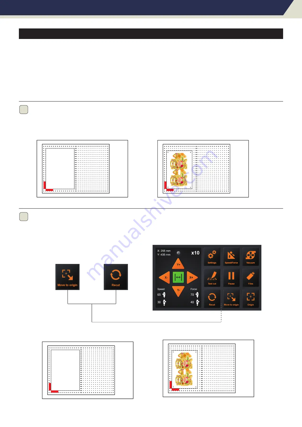
Set the origin, or move the carriage directly above the first mark to determine the origin. then start working.

*Do not interrupt data suddenly during transmission.

*The position of the placed media can be marked to facilitate the placement of the next media.

Chapter 3: Convenient Functions

3.6 Duplicate Cutting

Supplement 

• Do not send new data to plotter while copying. Cutting data in the buffer memory will be cleared.

• It can not copy if data is more than 1 MB because it cannot be stored in the buffer memory of the plotter.

• Watch out that it does not fall out of media when cutting with copy function.

• If the original cutting data to be copied starts away from the origin point, copied cutting will also start away from 

   the origin point. To avoid wasted space, create the cutting data close to the origin point.

First job

First job

2

After the first job, remove the media. Place the next media in the first media position. 

Press “Move to origin” will return to the origin and then press “Recut”,the cutter will start repeating the last job.

*The error of the marked position cannot exceed 1CM.

Second job...

Second job...

Page 25

Summary of Contents for FC-500VC

Page 1: ...USER S MANUAL FC 500VC PRECISION ACCURACY...

Page 2: ...high cutting quality and optimal productivity be sure to read this User s Manual thoroughly prior to use No part of this publication may be reproduced stored in a retrieval system or transmitted in an...

Page 3: ...operations immediately after completion of operations and when setting the cutting plotter functions the carriage Y bar will move to the origin position and other parts which are not fixed may move s...

Page 4: ...ipment 2 1 Stand and Cutter installation 11 2 2 Air pump installation 12 13 2 3 Use of tools 14 15 Blade holder Pen holder Creasing tools Type of blade 2 4 Attaching a tool 16 2 5 Connecting to the Co...

Page 5: ...24 Normal Stop Abnormal Stop 3 6 Duplicate Cutting 25 3 7 Offline output 26 3 8 Setting 27 30 Calibrate Cutter Size Offset Calibration Operating Mode About Page 4 Chapter 4 Troubleshooting and Mainten...

Page 6: ...Chapter 1 Product Summary 1 1 Machine Specifications 1 2 Accessories List 1 3 Product Introduction 1 4 Control Panel Product Summary Page 5...

Page 7: ...glossy paper Item Power consumption Operating environment Guaranteed accuracy environment Weight Compatible OS Compatible Standards Digital servo system Flatbed Vacuum suction 700 mm s 10 to 700 mm s...

Page 8: ...x 1pc Ethernet cable x 1pc Blade holder x 1pc Pen calibration tool x 2pcs Creasing tool x 1pc Creasing head x 1pc Pen x 5pcs Relief value x 1pc Silencer x 1pc Transfer hose x 1pc Hex Key x 1pc Philli...

Page 9: ...g plotter on and off 9 Network LAN interface connector The connector used when connecting this cutting plotter with the network LAN interface cable 10 U Disk port The port that is used only for the US...

Page 10: ...g 6 Cancel Cancel the job after the work is paused Page 9 Setting Machine calibration and system information Speed Force To set speed force of tool1 tool2 Vacuum To toggle of vacuum suction ON fast st...

Page 11: ...Chapter 2 Installation Equipment 2 1 Stand and Cutter installation 2 2 Air pump installation 2 3 Use of tools 2 4 Attaching a tool 2 5 Connecting to the Computer Installation Equipment Page 10...

Page 12: ...eams phillip screws 4 and phillip screwdriver be used Finally Put machine on floor stand hex screws 4 and hex key be used Note Please check labels on machine and stand to ensure correct direction and...

Page 13: ...econd connect Relief value into Transfer tube 1 on the top and tighten it connect Silencer into Transfer tube 2 and tighten it Finally Connect Transfer hose into Transfer tube on the right and tighten...

Page 14: ...Chapter 2 Installation Equipment 4 Note The transfer hose need to be passed through beam cover Page 13...

Page 15: ...blade seat Finally screw the blade holder cap to complete the installation and replacement of the blade The length of the blade is also adjusted by the blade holder cap Blade holder blade holder cap...

Page 16: ...ool cap as shown Pen holder Chapter 2 Installation Equipment 1 2 3 pen holder cap pen holder pen Finally screw the Calibration tool cap to complete the installation and replacement of the pen Creasing...

Page 17: ...ers the blade tip may be protruding Take care not to cut your fingers caution When mounting the tool in the tool holder please note the following Push the tool all the way into the holder until its fl...

Page 18: ...n via USB interface Connection via Network LAN interface Make sure that the power switch is turned off o side caution Supplement To use the network LAN interface the environment that can connect the c...

Page 19: ...power wait over 10 seconds before turning on it again otherwise problems may occur with the display Supplement The vacuum pump is supplied as a standard accessory No other air pump models are availab...

Page 20: ...ent Functions 3 1 Loading the Media 3 2 Move the Tool Carriage 3 3 Setting the Origin Point 3 4 Running Cutting Tests 3 5 Stop Cutting 3 6 Duplicate Cutting 3 7 Offline Output 3 8 Settings Convenient...

Page 21: ...the four corners using a drafting tape When the media is floating if the plunger tip cutter blade or ballpoint pen has contact with it it can affect the finish quality Or the cutting plotter body mig...

Page 22: ...ITION key When the cut is over the tool carriage will stop at a certain position then press the Move to origin button to return to the original point It can be used with Recut for Duplicate Cutting Wh...

Page 23: ...tion Y X Original origin point New origin point 1 You can press the POSITION button keys to move the tool to the new origin point 2 Press the Origin key and the new origin has been set The white text...

Page 24: ...l 2 2 1 If blade holder are placed in the tool holder 1 and creasing tool are plased in the tool holder 2 You can adjust the blade speed and force Turn on the speed and pressure buttons and adjust Cli...

Page 25: ...press the Start again After the work is paused Press the Cancel if you want cancel the job Abnormal stop During the work if you encounter an emergency you can press the emergency stop switch Rotate t...

Page 26: ...MB because it cannot be stored in the buffer memory of the plotter Watch out that it does not fall out of media when cutting with copy function If the original cutting data to be copied starts away f...

Page 27: ...ctions 3 7 Offline Output Supplement The Windows prohibited characters etc cannot be used Limit of the number of display characters is 8 characters Extension is plt Dedicated data that was preliminari...

Page 28: ...3 Use a ruler to measure the rectangle of the draw and input the measurement result to Measured Rectangle 4 Press Calc it s finished The program will automatically calculate the exact value Chapter 3...

Page 29: ...replaced with pen calibration tool first 2 Press Auto then machine will be draw two circle and two tangent square Then machine will automatically input the calibrated parameters 3 Press Return offset...

Page 30: ...al Common mode Perfect speed and precision Precision It is suitable for high precision work The accuracy is priority and the speed will be slowed down Hi speed It is suitable for large format work spe...

Page 31: ...de and update Page 30 Model The model of cutter Machine SN The series number of the cutter every machine has a unique number MB Ver The version of the mainboard MB SN The series number of the mainboar...

Page 32: ...Chapter 4 Troubleshooting and Maintenance 4 1 The error information of cutter 4 2 Maintenance 4 3 Exploded drawings and part lists Troubleshooting and Maintenance Page 31...

Page 33: ...work is completed Drawing The cutter is drawing a calibration file Oversize Working width exceeds the actual working width of the machine Modify the working size please pay attention to the actual wor...

Page 34: ...tion X1 Oversize Y1 Oversize X2 Oversize Y2 Oversize Restart cutter 1 Change the material position and reset the origin 2 Reduce the size of file Restart cutter 1 Change the material position and rese...

Page 35: ...nzene alcohol or similar solvents to clean the casings they will damage the casing s finish 3 If the writing panel is dirty please clean using a dry cloth Do not use benzine thinners or similar solven...

Page 36: ...Chapter 4 Troubleshooting and Maintenance 4 3 Exploded drawings and part lists Page 35 1 4 5 7 10 11 12 13 9 14 16 17 8 2 3 6 15 23 18 22 19 21 20 Exploded drawing for cutter...

Page 37: ...X cable 26 Y cable 20 Transfer board Emergency stop switch Panel Power supply Servo motor FC500VC 001 FC500VC 002 FC500VC 003 FC500VC 004 FC500VC 005 FC500VC 006 FC500VC 007 FC500VC 008 FC500VC 009 FC...

Reviews:

Related manuals for FC-500VC