ER SERIES ELECTRIC FRYERS - REMOVAL AND REPLACEMENT OF PARTS
F35613 (September 2003)
Page 12 of 48
POWER SUPPLY BOX
COMPONENTS
WARNING:
DISCONNECT THE
ELECTRICAL POWER TO THE
MACHINE AND FOLLOW LOCKOUT
/ TAGOUT PROCEDURES. THERE
MAY BE MULTIPLE CIRCUITS. BE
SURE ALL CIRCUITS ARE
DISCONNECTED.
CAUTION: Certain components in this system
are subject to damage by electrostatic discharge
during field repairs. A field service grounding kit
is available to prevent damage. The field service
grounding kit must be used anytime a control
board is handled.
1.
Remove the control panel as outlined under
CONTROL PANEL.
2.
Disconnect lead wires then remove the
component being replaced.
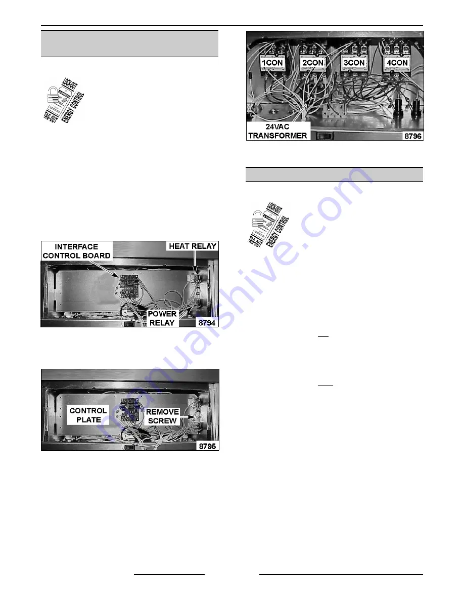
A.
If removing, contactor(s), transformer, or
filter relay, continue with procedure.
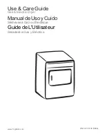
3.
Remove screw securing control plate to box.
A.
Grasp control plate on the right side at the
top, and pull out until left side holding tab
clears slot.
4.
Disconnect lead wires then remove the
component being replaced.
5.
Reverse procedure to install the replacement
component and check for proper operation.
HEATING ELEMENTS
WARNING:
DISCONNECT THE
ELECTRICAL POWER TO THE
MACHINE AND FOLLOW LOCKOUT
/ TAGOUT PROCEDURES. THERE
MAY BE MULTIPLE CIRCUITS. BE
SURE ALL CIRCUITS ARE
DISCONNECTED.
CAUTION: Do not sharply bend and kink the
capillary tube or the temperature probe, or
damage may occur.
1.
Remove basket hanger or lift arm(s) if basket
lift option is installed.
2.
Raise heating elements.
A.
If replacing left heating element, loosen
high limit bulb and capillary tube clamps.
Remove high limit bulb and capillary tube
from clamps then position away from
element.
B.
If replacing right heating element, remove
temperature probe clamps and position
temperature probe away from element.
Summary of Contents for ERC50
Page 35: ...ER SERIES ELECTRIC FRYERS ELECTRICAL OPERATION F35613 September 2003 Page 35 of 48 ...
Page 37: ...ER SERIES ELECTRIC FRYERS ELECTRICAL OPERATION F35613 September 2003 Page 37 of 48 ...
Page 45: ...ER SERIES ELECTRIC FRYERS TROUBLESHOOTING F35613 September 2003 Page 45 of 48 NOTES ...
Page 46: ...ER SERIES ELECTRIC FRYERS TROUBLESHOOTING F35613 September 2003 Page 46 of 48 NOTES ...
Page 47: ...ER SERIES ELECTRIC FRYERS TROUBLESHOOTING F35613 September 2003 Page 47 of 48 NOTES ...