Indicators and control elements
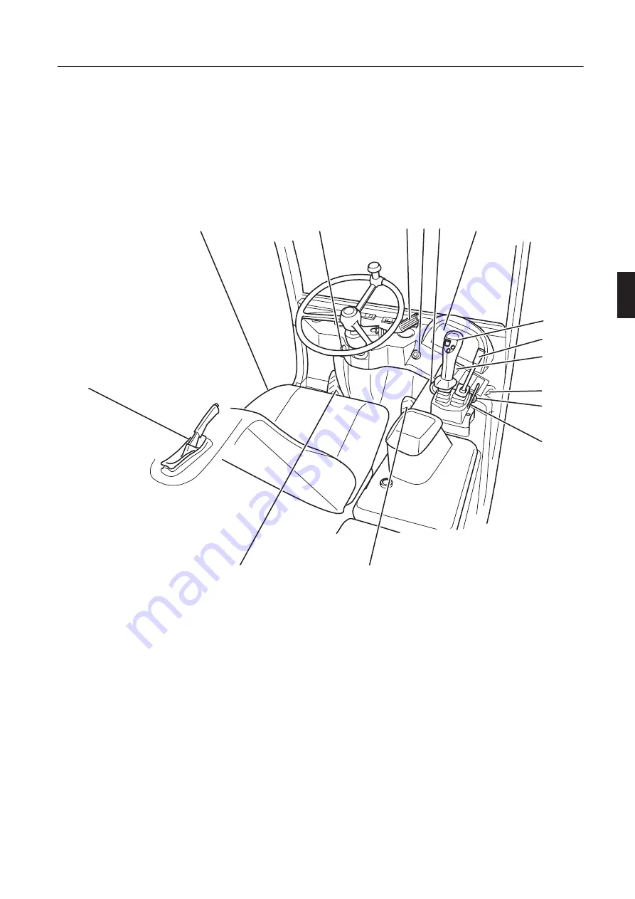
Operator's stand - control elements
25
Indicators and control elements
Operator's stand - control elements
Before taking the machine into operation you should become acquainted with the location and function
of all gauges and control elements. You should therefore thoroughly read these operating instructions.
Your safety is concerned!
M200009A
1
2
3
4
7
10
13
14
15
12
6
8
5
9
11
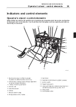
1 Multi function lever to lift/tip the bucket
Operation of differential lock and driving
2 Control lever, locking of quick change equipment
carrier and special hydraulics
3 Locking for working hydraulics
4 Driver's seat
5 Hand brake lever
6 Socket
7 Blower switch 3-steps
8 Temperature control - heater
9 Switch bar
10 Dashboard (control/warning lights), gauges
11 Ignition switch
12 Hazard light switch
13 Light switch/direction indicators/warning horn/
windscreen wiper-washer system, front
14 Drive pedal
15 Inching-brake valve
Summary of Contents for L20B
Page 1: ...OPERATOR S MANUAL Ref No VOE21A1000083 English CST Printed in Sweden ...
Page 26: ...Safety 24 Transport ...
Page 40: ...Indicators and control elements 38 Levers and switches ...
Page 48: ...Travel 46 Starting the engine ...
Page 90: ...Maintenance 88 Maintenance every 1500 operating hours ...
Page 110: ...Alphabetic register 108 Ref No VOE21A1000083 English CST Volvo Konz Printed in Sweden ...

