background image

Attachments - optional equipment

98

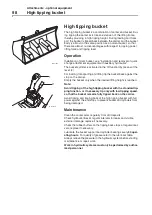
High tipping bucket

High tipping bucket

The high tipping bucket is a combination of carrier and bucket. Dur-
ing tipping the carrier acts like an extension of the lifting frame,
thereby providing a high tipping height. During loading and trans-
port the bucket is tipped back between the carrier and the bucket
body is almost in the same position as a normal bucket, so that
there are almost no disadvantages with respect to ripping power,
lifting force and tipping load.

Operation

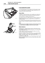
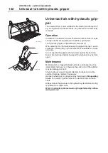
Installation of clam bucket, see "Installation and removal of quick
change attachment equipment with auxiliary hydraulics".

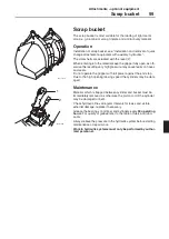
The bucket cylinder is activated in the 'tilt function' by means of the
lever (2).

For loading, transporting and lifting tip the bucket back against the
stop on the carrier.

Empty the bucket only when the desired lifting height is reached.

Note:

Avoid tipping of the high tipping bucket with the standard tip-
ping function, or if necessary tip only with low tipping speed,
so that the bucket remains fully tipped back on the carrier.

Avoid tipping and tipping back of the high tipping bucket with full
power against the end stops to prevent bucket and cylinders from
being damaged.

Maintenance

Clean the carrier arms regularly from dirt deposits.

Check hydraulic lines at regular intervals for leaks and visible
external damage, replace if necessary.

Check the rubber buffers on the tipping back stops at regular inter-
vals, replace if necessary.

Lubricate the bucket support and cylinder bearings every

50 oper-

ating hours

. For quality of grease refer to the lubricant table.

Always relieve the pressure in the hydraulic system before starting
maintenance or repair work.

Work in hydraulic systems must only be performed by author-
ized personnel.

M300099A

M200054A

2

1

Summary of Contents for L20B

Page 1: ...OPERATOR S MANUAL Ref No VOE21A1000083 English CST Printed in Sweden ...

Page 2: ...te of California to cause cancer birth defects and other reproductive harm California Proposition 65 Warning Battery posts terminals and other related accessories contain lead and lead compounds chemicals known to the State of California to cause cancer and other reproductive harm Wash hands after handling ...

Page 3: ...to improve our products and reserve therefore the right to implement design changes and improvements if we are of the opinion that this may improve the performance and the abilities of the product With this however we do not commit ourselves to modify machines which have already been delivered and which are already in operation We also reserve the right to change data and equipment as well as inst...

Page 4: ...ctions for your own personal safety The driver must also be acquainted with and observe all warning and information decals which are attached to the wheel loader These operating instructions must be treated confidentially It is intended to be used only by the personnel working in your company Handing it over to a third party is prohibited All documents are subjected to the copyright law Become acq...

Page 5: ... attachments 47 Switching 48 Charging 49 Attaching and removing attachments 50 Differential lock 53 Stopping and parking the machine 54 Maintenance 55 Maintenance instructions 55 Tires 60 Brake system 62 Windscreen washer system 63 Toothed belt 64 Running in instructions 65 Lubrication and maintenance plan 66 Maintenance every 10 operating hours 69 Maintenance every 100 operating hours 75 Maintena...

Page 6: ...Table of contents 4 Special hydraulics 104 4 Hydraulic circuit electrically switchable 105 Manual inching function 106 Alphabetic register 107 ...

Page 7: ...ine must be equipped for such work For further information please contact the manufacturer or your dealer Engine Volvo D3D C E is a four cylinder four stroke diesel in line engine Direct fuel injection with oil air cooling Power transmission Hydrostatic drive fully controllable under load also for reversing of direction forward and reverse and in all speed ranges Maximum pushing power is achieved ...

Page 8: ...ke Drum brake on front axle hydraulically actuated via inching brake pedal Parking brake mechanical activation front axle drum brake Noise emission values Sound pressure level LpA determined acc to ISO 6396 at the operator s stand 74 dB A Sound pressure level LwA determined acc to ISO 6395 around the machine is see sticker on machine ...

Page 9: ...ral parts of the machine The CE sign therefore cov ers also our attachments We do not assume liability for attach ments made by other manufacturers Materials which have an effect on noise such as noise insulating noise reducing or noise absorbing materials must not be changed or removed It is also prohibited to cut holes into the cabin or the engine compartment because this would have a negative e...

Page 10: ... 3471 1994 and SAE 1040 APR 88 The cabin also has the FOPS approval according to ISO 3449 1992 SAE J231 JAN 81 Any planned changes must first of all be checked by the technical department to find out whether the change is permitted within the framework of the certification examinations It is of utmost importance that both the employees as well as the management are fully acquainted with the instru...

Page 11: ...vehicle identification number serial no perm total weight perm front rear axle load and year of manufacture 3 Cabin ROPS FOPS Plate The plate is located in the battery box on the right hand side Includes model designation ROPS FOPS number and max permissible machine weight 4 Engine identification plate contains design engine number as well as perform ance data The engine serial number is additiona...

Page 12: ...s which are attached to the wheel loader Stickers and decals which are missing or have been damaged must be immediately replaced Apart from that the decals must be kept in a legible i e clean condition The spare parts number ordering number is printed on the respective decal or can be found in the spare parts catalogue 4 14 7 11 M200002A 10 13 8 9 5 3 9 10 2 12 9 10 6 1 10 ...

Page 13: ...ign Articulation area Nobody is allowed stay within the unsecured articulation area 4 Warning sign Engine hood only to be opened when the engine has stopped Due to the risk of injury by rotating parts it is dangerous to open the engine hood while the engine is running 5 Caution sign Battery disconnection switch The battery disconnecting switch must always be switched off for longer resting periods...

Page 14: ... must be used to fill up or when changing the oil 9 Caution sign Loading or unloading Lifting Fastening points for lifting the machine 10 Caution sign Lashing Fastening point for transporting the machine 11 Caution sign Lever functions 12 Caution sign Fuse assignment This decal is located on the service door see electric system 13 Caution sign Fuses and relays This decal is located in the engine c...

Page 15: ...N lbf 35 0 7868 30 5 7644 28 0 6295 25 0 5620 36 5 8206 A Overall length mm ft in 5035 16 5 5135 16 8 5195 17 0 5295 17 3 5005 16 4 5510 18 1 L Lifting height mm ft in 4060 13 3 4140 13 6 4190 13 7 4285 14 1 4070 13 3 4890 16 0 V Bucket width mm ft in 1650 5 1 1650 5 1 1800 5 9 1800 5 9 1650 5 1 1800 5 9 a1 Turning circle diameter mm ft in 8210 26 9 8260 27 1 8410 27 5 8460 27 7 8220 26 9 8620 28 ...

Page 16: ...gn 4 in line Bore stroke 94 112 mm 3 7 in 4 4 in Displacement 3108 cm3 190 cu in Combustion method Direct injection Cooling Oil Air Electric system System voltage 12 V Battery voltage 12 V Battery capacity 88 Ah Three phase generator 1120 W 80 A Starter power 2 2 kW 3 0 hp Travel speeds Gear 1 turtle forward reverse 0 4 5 km h 0 2 8 mph Gear 2 rabbit forward reverse 0 20 km h 0 12 mph Chassis Max ...

Page 17: ...ate 52 l min 13 7 US gpm at engine speed 2300 min 38 3 r s Pressure relief setting 20 MPa 2905 psi One double acting tipping cylinder One double acting lift cylinder Lifting time under load 6 0 sec Lowering time empty 4 0 sec Tipping time 1 5 sec Tipping back time 2 0 sec Filling capacities Fuel tank 60 l 15 8 US gal Engine incl filter 10 5 l 2 8 US gal Hydraulic system incl tank 60 l 15 8 US gal ...

Page 18: ... for a person knowingly to remove or render inoperative such a device or element of design after the sale and delivery to the ultimate purchaser The law provides a penalty of up to 2 500 for each violation An example of a prohibited modification is the recalibration of the fuel system so that the engine will exceed the certified horsepower or torque You should not make a change to an EPA certified...

Page 19: ...med on the non road engine Volvo recommends that the owner keep all records and receipts of such maintenance These records and receipts should be transferred to each subse quent purchaser of the non road engine Service performed by your local dealer Your local dealer is best qualified to give you good dependable service since he has trained service technicians and is equipped with genuine original...

Page 20: ...tions below 32 ºF 0 ºC the use of lighter distillate or higher cetane level fuel are recommended Final boil ing point max 660 ºF 349 ºC and cetane min 45 To avoid excessive deposit formation and to minimize the emis sions of sulfur dioxide into the ambient air the sulfur content of the fuel should be the lowest available The diesel fuels recommend ed for use in Volvo engines should meet ASTM desig...

Page 21: ... be operated on public roads The wheel loader is a self propelled working machine in accord ance with 18 para 2 No 1 motor vehicle construction and use regulation and does therefore not have to be registered and is free of tax The type approval must always be with the machine and it must be presented to authorized persons on request The loader may only be operated on public roads with the equipmen...

Page 22: ... to the machine which could impair the safety without the permission of the machine manufacturer This applies for the installation and adjustment of safety equipment and valves as well as for the welding on load bearing parts Driving on public roads operation After work the loader must be cleaned from coarse dirt Empty the bucket completely no objects must be transported in the bucket Cover the fr...

Page 23: ...rking attachment to the ground Apply the parking brake Shut the engine down Check whether all switches and control elements are switched off or out of function Close or lock all covers windows and doors Block the wheels with a wedge Make sure that the loader does not protrude into the road If this cannot be avoided stand up warning signs as specified in the motor vehicle construction and use regul...

Page 24: ...1 km 0 625 mile After towing loosen the nuts 1 on the high pressure relief valves A and B and back the screws 2 out to the stop Retighten the nut 1 The original setting of the high pressure relief valves is thereby reestablished For longer distances the machine must be transported with a transport vehicle trailer Note For recovery work the towing hitch may be loaded up to max 3500 daN 25813 lbf ft...

Page 25: ... or rolling off Caution sign Lashing 1 Fastening eyes on front frame 2 Fastening eyes on rear frame towing hitch Lifting the machine To lift the machine use the specified lifting points and make sure the articulated joint is locked The locations of the lifting points can be seen in the illustration Caution sign Loading or unloading Lifting 1 Lifting fastening eyes on the front frame 2 Lifting eyes...

Page 26: ...Safety 24 Transport ...

Page 27: ...00009A 1 2 3 4 7 10 13 14 15 12 6 8 5 9 11 1 Multi function lever to lift tip the bucket Operation of differential lock and driving 2 Control lever locking of quick change equipment carrier and special hydraulics 3 Locking for working hydraulics 4 Driver s seat 5 Hand brake lever 6 Socket 7 Blower switch 3 steps 8 Temperature control heater 9 Switch bar 10 Dashboard control warning lights gauges 1...

Page 28: ...ake 10 Travel direction indicators 11 Headlights 12 Preheating 13 Forward travel 14 Reverse travel 15 Travel range gear 2 rabbit 16 Travel range gear 1 turtle 17 Fuel level gauge 18 Operating hour meter When reaching the limit values the warning buzzer sounds as an audible warning signal only when engine is run ning Engine oil temperature Engine oil pressure Hydraulic oil temperature Hydraulic oil...

Page 29: ... Filling capacity see technical data 2 Differential lock The control light lights up when the differential lock is activated 3 Hydraulic oil filter The filter element must be changed when the control light lights up 4 Hydraulic oil temperature If the hydraulic oil temperature is impermissibly high the control light lights up and the warning buzzer sounds Shut the engine down check the hydraulic oi...

Page 30: ...uzzer sounds stop the wheel loader shut the engine down and clean or replace the air filter immediately 7 Engine oil pressure If the engine oil pressure drops below a permitted value the control light lights up and the warning buzzer will sound Stop the wheel loader shut the engine down perform trouble shooting if necessary inform the customer service 8 Engine oil temperature If the engine oil tem...

Page 31: ... the indicator switch 11 Headlights The control light lights when the travel light is switched on 12 Preheating The control light lights during preheating The control light lights only when the ignition switch is in position 1 13 Forward travel 14 Reverse travel When selecting a travel direction forward reverse via the multi function lever the control lights indicate the selected travel direc tion...

Page 32: ... in the fuel tank If the pointer is in the red sector or the control light 1 lights up the machine needs refuel ling Filling capacity see technical data 18 Operating hour meter The operating hours of the wheel loader are shown in minutes and hours Perform the maintenance tasks accordingly ...

Page 33: ...ht green Switch depressed Permanent wiping switched on Press switch again and hold it Washing pump and wiper motor switched on The washing pump remains switched on as long as the switch is depressed 3 Working headlights front option When actuated both function LED and symbol light green Switch depressed Working headlights switched on The working headlights can only be switched on together with the...

Page 34: ...acon switched on When switching the ignition off while the flashing beacon is on the flashing beacon will stay on 6 7 8 Water pump for road sweeper Optional equipment Additional pump optional equipment Locking for attachment carrier option When actuated both function LED and symbol light green Switch depressed Function switched on M200035A 5 6 7 8 M200036A M200037A ...

Page 35: ...on the wheel loader will flash at the same time 13 Light switch direction indicators warning horn windscreen wiper washer system Direction indicator warning horn Lever forward left hand direction indicator Lever backward right hand direction indicator Button depressed warning signal Headlights Lift the lever towards the steering wheel full headlights Windscreen washer system Pull the ring towards ...

Page 36: ...ch braking pedal while the drive pedal is fully kicked down highest possible lifting speed of the bucket reduces the travel speed to a minimum e g when approaching a truck In the last third of the pedal movement the friction brake drum brake on the front axle will apply 5 Hand brake It works from the hand brake lever via a Bowden cable to the drum brake on the front axle When selecting a travel di...

Page 37: ...e opening for circulation air operation opened Fan operation Turn the temperature regulator 8 to the desired position Set the blower switch 7 to one of the three possible steps Intake opening A for circulation air operation closed The air distribution is controlled by adjusting the air discharge noz zles B The air intake for cabin heating and fresh air is equipped with a dust filter located at the...

Page 38: ...ges 1 and 2 are selected when actuating the button The control light lights up D Actuating this button switches from Forward trabvel or Back ward travel to Neutral position the machine comes to a halt E Actuating and holding the button engages the differential lock F Special function option Actuating and holding the button activates the function ATTENTION The differential lock must only be engaged...

Page 39: ... back D Tipping forward E Lifting Lever 2 Locking quick change equipment carrier and special hydraulics Neutral F Unlocking G Locking with notch C Tipping back D Tipping forward ATTENTION For road travel and maintenance work the working hydrau lics must be blocked against unintended actuation M200045A 1 C E D A B M200046A 2 C G D F M200047A ...

Page 40: ...Indicators and control elements 38 Levers and switches ...

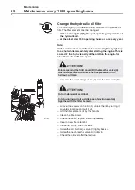
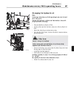
Page 41: ...rt it until it bottoms and pull it back out The dipstick should generally be covered with oil up to the upper mark Top up oil if necessary For quality of oil refer to the lubrication chart Checking the oil level in the travel working and steering hydraulics The above mentioned assembly groups have a common oil household With the loading equipment lowered the bottom oil level inspec tion glass must...

Page 42: ... brake oil to the MAX mark Driver s seat 1 Backrest adjustment 2 Horizontal adjustment 3 Height adjustment 4 Weight adjustment 50 120 kg 88 286 lbs Vibration damping on the driver s seat The approved vibration acceleration azw measured according to ISO 2631 part 1 is between 0 5 and 2 5 m s2 if the machine is used for purposes it is intended for ATTENTION Brake oil quality mineral oil see lubrican...

Page 43: ...ank Brake oil level correct Water in the provision container for the windscreen washer sys tem Always climb onto or off the machine with your face towards the machine and use access steps and grips always have both hands and one foot or both feet and one hand on the machine Do not jump off Wear safe clothing Wear a hard hat Do not drive the machine if you are under the influence of alco hol medica...

Page 44: ...ntrol light 12 preheating has gone out turn the ignition key to position II and start As soon as the engine starts to run by itself release the ignition key returns to position I Do not start for longer than 25 seconds without interruption If the engine does not start turn the ignition key back to position 0 and repeat the starting procedure Once the engine is run ning the above mentioned control ...

Page 45: ...nd or below the freezing point the wheel loader must be warmed up by running the engine at medium speed Drive the wheel loader warm by driving it in gear 1 turtle for about 5 10 minutes with approx 1 2 engine speed If possible the bucket or lifting frame should be moved several times by actuating the control levers for the working hydraulics ...

Page 46: ...tivated Flashes when the engine can be started C Keys for input of code D Key to release the code E Key to change the code The 6 digit secret code see delivery note of the immobilizer has been programmed in the factory Insert the ignition key into the ignition switch and turn it to posi tion I Enter the secret code 6 digit press key D and start the engine Note If the code is incorrectly entered re...

Page 47: ...e been programmed Insert the ignition key into the ignition switch and turn it to position I Enter the access code dealers technical personnel and press key E Enter the access code for users driver rental customer a row of numbers 6 digit of your choice Press key E to confirm this programming sequence For safety reasons this access code must be entered twice Enter the access code 6 digit press key...

Page 48: ...Travel 46 Starting the engine ...

Page 49: ... approx 10 mm Shift lever 2 to middle position neutral Turn the cock valve on the attachment carrier to position B A Cock valve in position Open B Cock valve in position Closed C Locating pin D Locking pin ATTENTION Before each ride ensure that the attached device has been locked and secured ATTENTION Check whether the working attachment is properly locked and secured by actuating lever 1 from Tip...

Page 50: ... the selected travel direction to neutral or to change the travel direction at higher speeds because the deceleration effect is very high Once the correct travel range has been activated operate the roll switch to the desired travel direction forward A or reverse B Make sure that no persons are within the danger zone of the loader and give a short signal with the warning horn always before setting...

Page 51: ...erate the lever 1 alternately several times quickly from tipping to tip ping back when entering into the material This eases entering of the bucket into the material During the transport of the picked up material the bucket should not be higher than 0 5 m 20 in above the ground You should never drive longer distances with a high raised loaded bucket When the lever 1 is in float position the bucket...

Page 52: ... have picked up the working attachment Actuate lever 2 Tipping back until the working attachment lifts off the ground Shift lever 2 backwards until the locking pins D protrude from the receiving bores of the working attachment for approx 10 mm Shift lever 2 to middle position neutral Shut the engine down Turn the cock valve on the attachment carrier to position B A Cock valve in position Open B Co...

Page 53: ...e bucket road sweeping machine etc Drive the loader forward up to the working attachment Turn the cock valve on the attachment carrier to position A Shift the lever 1 to Lifting until the centring pins C of the SW carrier see illustration have picked up the working attach ment Actuate lever 2 Tipping back until the working attachment lifts off the ground Shift lever 2 backwards until the locking p...

Page 54: ...er Turn the cock valve on the attachment carrier to position A Start the engine Shift lever 2 forward until the locking pins are fully retracted from the receiving bores in the working attachment Operate lever 1 to Tipping and Lowering until the locating pins of the SW carrier are free Shift lever 1 to middle position neutral Drive the loader backwards away from the working attachment ATTENTION Ch...

Page 55: ...ntial lock is engaged control light 2 lights up If only one wheel of an axle turns when setting off with the differential lock engaged stop moving and operate the steering to ensure engagement of the lock The differential lock may be disengaged while driving ATTENTION The differential lock must only be engaged when the machine is standing ATTENTION When cornering on hard ground the differential lo...

Page 56: ...ut let it idle for a short while for temperature equalization To shut the engine down turn the key in the ignition switch to position 0 All control lights must go out Pull the ignition key out of the ignition switch when it is in position 0 Note Once tne engine is shut down ignition switch in position 0 the machine is automatically switched to neutral position and to gear 2 rabbit If possible park...

Page 57: ...so be engaged For maintenance work under the raised lifting frame this must be supported to prevent unintended lowering The stability of the wheel loader must be ensured for assembly maintenance and repair work When lifting the machine use the lifting eyes provided for this purpose Secure a jacked up machine by piling e g wooden beams crosswise underneath or by supporting with trestles Use only to...

Page 58: ...achine parked in hor izontal position The required filling quanity as well as the oil quality can be found in the lubrication table Oil level dipsticks and oil level inspection glasses are decisive for the oil levels Lubrication points lubrication intervals and lubricants can be taken from the lubrication and maintenance plan or from the lubrication table All hinges fork heads and other joints tha...

Page 59: ...ic system Before welding grinding and torch cutting paints must be stripped in an area of at least 10 cm 4 in around the affected location Heated paints emit health threatening vapours which could cause irritations and highly health damaging effects in case of repetitive contact Apart from the health damaging effects paint also results in a poor connection of the weld which could cause a later fai...

Page 60: ...e fighting measures and if necessary alarm the fire brigade Check every day that machine and equipment such as guards are free off dirt and oil This reduces the risk of fire and it also helps to detect faulty and loose components ATTENTION Smoking and open fire is prohibited when refueling or when performing maintenance work on the fuel system ATTENTION Welding and grinding work should only be per...

Page 61: ...lter etc Check hoses and pipes for fuel hydraulic oil and brake fluid at reg ular intervals for leaks and visible external damage replace if necessary Electric wires must be protected against wear and checked for possible damage replace if necessary Unprotected electric wires must not be routed in contact with oil or fuel lines It is of particularly importance to keep the area around the battery a...

Page 62: ...ze and rims can be taken from the type approval Tires Air pressures bar psi front rear 10 16 5 3 75 54 3 75 54 12 16 5 3 75 54 3 75 54 10 5 18 3 25 47 2 5 36 10 5 80 18 3 0 44 2 5 36 12 0 18 2 25 32 2 0 29 12 5 18 2 25 32 2 0 29 12 5 80 18 2 5 36 2 0 29 15 5 55 R18 2 75 40 2 5 36 12 5 20 2 25 32 2 0 29 275 80 R18 2 5 36 2 5 36 320 80 R18 2 5 36 2 25 32 335 80 R18 2 5 36 2 25 32 340 80 R 18 2 5 36 ...

Page 63: ...tread of a tire After checking and filling screw the valve cap back on For special applications e g on sand the air pressure may be changed after consulting the customer service department or the tire manufacturer The adherence to the specified air pressure has a decisive influence on the lifetime of the tires For the tires driving with a too low air pressure means higher kneading work higher temp...

Page 64: ... 500 operating hours Inspection of parking brake Apply the parking brake Start the engine Raising the working attachment transport position Preselect forward backward travel neutral position With the travel system switched off and an empty bucket the parking brake must be able to hold the machine on a 20 slope ATTENTION The parking brake must only be checked in a specially secured location Make su...

Page 65: ...ce the wiper blades if they leave stripes on the windscreen Container windscreen washer system The container for the windscreen washer system for front rear windscreens is located in the engine compartment on the left hand side arrow Fill up container as necessary With temperatures around or below freezing make sure that a sufficient amount of anti freeze is added M200060A ...

Page 66: ...thed belt A visual examination of the toothed belt is no longer necessary Replacement intervals for the toothed belt are every 5000 operating hours but at the latest after 5 years replacement must be performed by authorized personnel ...

Page 67: ...tightening torque 290 Nm 213 lbf ft After a wheel change the wheel nuts must also be tight ened every day during the first week First maintenance after 500 operating hours For further maintenance intervals refer to the lubrication and main tenance plan Oil change in front rear axle with splitter gear First maintenance also for service exchange and new compo nents ...

Page 68: ...1A A 500h 1500h 1000h 100h Pos 10h in 0 3 mm 0 012 in 0 5 mm 0 020 in ex 10h 100h 500h 1000h 1500h Pos 10h 100h 500h 1000h 1500h Pos 10h 100h 500h 1000h 1500h Pos 6 5 A 15 P 11 9 3 16 17 18 2 20 19 7 W W W W P P R W P 8 13 1 12 10 W P W P R R P W 14 4 P FUEL OIL max OIL AIR a in ex W OI L ...

Page 69: ...em engine and travel hydraulics 77 P R Maintenance every 1000 operating hours First all 10 and 100 hour intervals Perform the following additional service work 9 Change the engine oil 78 W approx 10 5 litres 2 8 US gal 10 Changing the oil filter 79 W 2904941 11 Check the V belts 80 P 12 Change the fuel filter cartridge 81 W 11708556 13 Fuel lift pump clean the strainer 81 R 14 Water separator in f...

Page 70: ...e factory see sticker on filler neck only the oil quality specified on the sticker must be used to fill up or when changing the oil Note BIO oils and mineral oils carbon hydrogen oil must be disposed of separately Mixing is prohibited Place of use Quality required viscosity at ambient temperature SAE KL API specification CF 4 CG 4 CH 4 ACEA specification E1 E3 96 E4 98 Engine 10 W 40 15 W 40 5 W 3...

Page 71: ... starting For an exact oil level check the engine must be shut down again after approx one minute In this case the entire oil system is filled and after shutting the engine down your actually measuring the oil quantity in the oil sump which is available while the engine is run ning Before longer operating periods of the engine we strongly advise you to perform this double check of the engine oil l...

Page 72: ...nly if the control light in the dash board lights up the filter must be immediately cleaned or if necessary replaced The air filter service intervals depend on the amount of dust in the air and can therefore not be determined precisely Under extremely dusty conditions daily clean may be required Check the air lines filter engine for leaks during every main tenance Replace defective parts tighten l...

Page 73: ... Safety cartridge C While servicing the main cartridge paper cartridge the safety cartridge remains inside the air filter Safety cartridges must be renewed After three times servicing of the main cartridge The number of services exchange or cleaning of the main cartridge must be marked in the respective fields on the safety cartridge At the latest after two years of use If the service indicator co...

Page 74: ...owl C off empty and clean it Cleaning the oil bath air filter Open the covers on the oil tank D Take the oil tank D and the filter element E out downwards Empty the oil tank and clean it Wash the filter element E out with diesel fuel Check the seals on the filter element for damage replace if nec essary Fill the oil tank D with new oil up to the level mark insert it together with the filter elemen...

Page 75: ...ator in the fuel system Before starting check for water and dirt in the inspection glass arrow and drain it off if necessary ATTENTION When working on the fuel system do not use open fire do not smoke ATTENTION Catch running out fluids and dispose of environmentally M200064A ...

Page 76: ...erating hours Articulated joint lubricating the bearings Lower the working attachments The hydraulic system must be without pressure Clean the grease nipples before greasing Sufficient lubrication if grease emerges from the bearing M200065A ...

Page 77: ...he working attachments The hydraulic system must be without pressure Clean the grease nipples before greasing Sufficient lubrication if grease emerges from the bearing Note In case of difficult working conditions the bearings must be greased every day ATTENTION When working in the danger area of the articulated joint the articulation lock must be applied M200066A ...

Page 78: ...rk Open the tank cover arrow Top up brake oil to the MAX mark Note Replace leaking and externally damaged brake hoses and brake lines immediately External damage are corrosion symptoms wear chafing squashing etc ATTENTION Brake oil quality mineral oil see lubricant chart ATTENTION For safety reasons change the brake oil every 2 years Catch the brake oil and dispose of environmentally M200067A ...

Page 79: ...intervals must be determined individually for each case Cleaning the cooling system Place a dirt collecting container underneath Remove the cooling air hood 1 Blow the engine out with compressed air starting from the air discharge side pay special attention to cooling fins and oil cooler Remove any dirt that has been blown into the air duct Do not subject sensitive engine parts such as generator w...

Page 80: ...u Engine oil change Perform the oil change when the engine is warm and shut down lubrication oil temperature approx 80 C 176 F Unscrew the cap from drain valve A Screw the drain hose B onto the drain valve Screwing the drain hose on opens the drain valve and allows the oil to flow out Once all old oil has run out unscrew the drain hose and screw the cap back on the drain valve Fill the new oil in ...

Page 81: ...w lubrication oil filter cartridge Screw the cartridge on by hand until the seal touches the sur face Tighten the lubrication oil filter cartridge for another half turn Check the lubrication oil filter cartridge for leaks ATTENTION Hot oil Danger of scalding Catch running out oil and dispose of environmentally together with the filter cartridge ATTENTION Excessive tightening of the filter may dama...

Page 82: ...e resting against the side of the V belt Press the push button 4 evenly under a right angle to the V belt 2 until the spring is noticeably released Lift the measuring gauge carefully without changing the posi tion of the indicator arm 1 Read the measuring value on the intersection arrow of scale 5 and the indicator arm 1 V belt tension Tensioning after initial installation 450 50 Nm 331 37 lbf ft ...

Page 83: ...ystem is not necessary Note A drop in engine power can be caused by a clogged fuel filter cartridge If the fuel filter cloggs rapidly check the fuel for any contami nation Clean the tank make sure it is properly closed Fuel lift pump clean the strainer Slacken the screw A and unscrew it Take the fuel strainer B out lid with strainer Clean the fuel strainer B with fuel depending on the condition yo...

Page 84: ...from the injection valves to the fuel tank replace if necessary However the fuel leakage lines and the connecting pieces must be replaced every 2 years at least Fasten the cylinder head cover Tightening torque 9 1 Nm 6 6 0 7 lbf ft Note Install a new valve cover gasket ATTENTION When working on the fuel system do not use open fire do not smoke ATTENTION Catch running out oil and dispose of environ...

Page 85: ...ulate the adjustment screw 5 with an Allen key 7 so that the correct valve clearance is reached after retightening the counter nut 4 Perform tests and adjustments on each cylinder Reassemble the cylinder hood with a new gasket Adjustment pattern for valve clearance adjustment Crankshaft position 1 Turn the crankshaft until both valves on cylinder 1 are overlap ping exhaust valve not yet closed inl...

Page 86: ... position loosen and unscrew the plug carefully Then bring the drain bore to bottom position and let the oil run out For filling turn the wheel hub until the word Oil level is in hori zontal position Fill in approx 0 3 litres 0 07 US gal of oil into each wheel hub until it starts to flow out Screw in the plugs A and B with new O rings Fill in oil through the filler level control bore C until it st...

Page 87: ...on loosen and unscrew the plug carefully Then bring the drain bore to bottom position and let the oil run out For filling turn the wheel hub until the word Oil level is in hori zontal position Fill in approx 0 3 litres 0 07 US of oil into each wheel hub until it starts to flow out Screw in the plugs A B and D with new O rings Fill in approx 1 litre 0 26 US of oil through the filler bore E on the g...

Page 88: ...idle speed Unscrew the air discharge valve C from the filter cover B Loosen the screws on the lid B unlock the lid by turning it counter clockwise and pull it out Lift the filter element out by the handle Clean the filter bowl Check the seals replace them if necessary Insert a new filter element Close the lid B check for leaks Screw the air discharge valve C tightly back in Screw the new breather ...

Page 89: ... the drain valve Screwing the drain hose on opens the drain valve and allows the oil to flow out Once all old oil has run out unscrew the drain hose and screw the cap back on the drain valve Install the new filter element Fill the fresh oil in through the filler neck B Oil filling quantity in case of an oil change approx 42 litres 11 1 US gal For quality of oil refer to the lubrication chart Check...

Page 90: ...Maintenance 88 Maintenance every 1500 operating hours ...

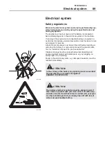
Page 91: ...e battery For removal disconnect the ground cable first for installation connect the positive cable first Cables and plugs must be marked before disconnecting and secured against contact with metal parts e g by plugging on safety caps or by insulating Faults in the electrical system e g damaged insulation must be rectified immediately ATTENTION In the vicinity of the battery any sparking must be a...

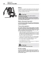
Page 92: ...h or Incor rect connection immediately damages the rectifier in the gener ator Before disconnecting battery cables shut down the electric power by the battery disconnecting switch In case of a fault in the electric system e g a faulty regulator compensate the increased water consumption of the battery Unscrew the caps and fill in distilled water up to approx 10 15 mm 0 4 0 6 in above the lead plat...

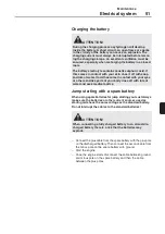
Page 93: ...ery and then the cable between the plus poles ATTENTION During the charging process oxyhydrogen will develop inside the battery A short circuit an open flame or sparks in the vicinity of the battery can cause an explosion The charging current must always be interrupted before remov ing the charging clamps An excellent ventilation must be ensured especially when recharging the battery in a closed r...

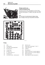
Page 94: ...al function lever 1 optional equipment K7 D release terminal 15 K16 Special function lever 2 optional equipment K8 Direction spool K17 Working head lights K9 Hand brake control warning buzzer K18 Speed dependent optional equipment M200081A M200082A X104 X112 X107 X108 X109 X110 V1 V2 V3 V4 V5 V6 V7 V8 V9 V10 X105 K18 K1 K7 K4 K14 K8 K5 K13 K10 K6 K15 K12 K11 K9 X106 X115 X111 X103 X102 X101 15 31 ...

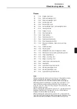
Page 95: ...e checked Function LEDs must light up F1 10 A Engine shut down F2 7 5 A Dimmed headlight left F3 7 5 A Dimmed headlight right F4 7 5 A Fender light left F5 7 5 A Fender light right F6 7 5 A Full headlight right full headlight control F7 20 A Heating blower F8 10 A Socket 1 pole F9 10 A Flashing beacon F10 15 A Seat heating F11 7 5 A Radio terminal 15 F12 7 5 A Dashboard illumination F13 15 A Road ...

Page 96: ...e engine compartment on the left hand side Note Use only fuses of specified capacity Ampere rating Risk of damage or burning of the printed circuit board Relay Fuses K21 Preheating time control K22 Fan motor for oil cooler F100 60 A Glow plug F101 40 A Fan motor for oil cooler M200083A K22 K21 F100 F101 ...

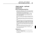
Page 97: ...ing device plug the electric plug for the water pump into the socket on the front frame During operation make sure that the height adjustable support ing wheels are adjusted to such a height that the horizontally adjusted broom drum only just touches the ground The weight of the road sweeping machine must always rest on the support ing wheels and not on the brushes If the brushes are adjusted too ...

Page 98: ...st no longer be used for work Check also the fastening parts to the fork frame for wear or cracks In case of damage or extensive play the fork lift attach ment must no longer be used for work Cracks in material at the wear points must not be repaired by welding In principle the driver is responsible for ensuring that the lifted load does not exceed the permitted machine and fork lift attach ment l...

Page 99: ...s such as rocks or tree trunks do not damage or distort the front flap The travel speed must be matched to the condition of the road Maintenance Material which is trapped between locking cylinder and rear clam must be immediately removed as otherwise the piston rod of the cylinder may be damaged or bent Check hydraulic lines at regular intervals for leaks and visible external damage replace if nec...

Page 100: ...carrier Empty the bucket only when the desired lifting height is reached Note Avoid tipping of the high tipping bucket with the standard tip ping function or if necessary tip only with low tipping speed so that the bucket remains fully tipped back on the carrier Avoid tipping and tipping back of the high tipping bucket with full power against the end stops to prevent bucket and cylinders from bein...

Page 101: ...operate the gripper with full power against the end stop Due to the high opening closing speed the cylinders may be dam aged Maintenance Material which is trapped between cylinder and bucket must be immediately removed as otherwise the piston rod of the cylinder may be damaged or bent Check hydraulic lines at regular intervals for leaks and visible external damage replace if necessary Grease the b...

Page 102: ...full power against the end stop Due to the high opening closing speed the cylinders may be dam aged Note To manoeuvre the shredder machine with the ball joint tip the clamshell bucket completely back and close the grab Maintenance Material which is trapped between cylinder and bucket must be immediately removed as otherwise the piston rod of the cylinder may be damaged or bent Check hydraulic line...

Page 103: ...o prevent the bucket and the cylinder from being damaged Wet or very dense material may affect the stability of the machine when the tip bucket is emptied Therefore no unnecessary turning movements should be performed when the lift arms are up and the bucket cylinder is fully extended Maintenance Check hydraulic lines at regular intervals for leaks and visible external damage replace if necessary ...

Page 104: ...cause leaks on hoses and seals Do not operate the gripper with full power against the end stop Due to the high opening closing speed the cylinders may be dam aged Maintenance Material which is trapped between cylinder and bucket must be immediately removed as otherwise the piston rod of the cylinder may be damaged or bent Check hydraulic lines at regular intervals for leaks and visible external da...

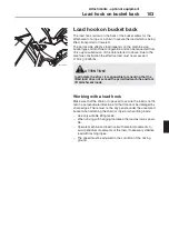
Page 105: ...ook Make sure that the chain or rope used to secure the load is not fit ted in a perpendicular direction and that it cannot be damaged by sharp edges There must not be any people under the unsecured bucket when attaching the chain or rope or when lifting loads Use only suitable lifting tackle When driving with hanging load keep the load as low as possi ble Operate machine and load hook with carefu...

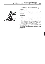
Page 106: ... only be activated when the engine is running Operate the push button F in lever 1 and hold it The special hydraulics function is enabled Locking unlocking the SW equipment carrier see Installation and removal of quick change attachment equipment with auxil iary hydraulics Attachment equipment Open Close Release the push button F standard function Up Down Float position Always relieve the pressure...

Page 107: ...accomplished by actuating and holding the push button arrow in the lever 2 Release push button arrow special hydraulics function e g SW equipment carrier lock unlock To relieve the pressure in the quick hydraulic couplings of the 4 hydraulic circuit shut the engine down turn the ignition switch to position I ignition and move the lever 2 with the push but ton arrow actuated several times forward a...

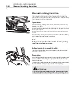
Page 108: ...ing valve arrow in clockwise direction close until the desired travel speed is reached Note During normal operation of the machine the rotary inching valve must be completely closed Adjustment of manual throttle The hand throttle cable arrow is located on the left hand side beside the driver s seat Operation Kick the drive pedal slightly down pull out the hand throttle cable arrow until the desire...

Page 109: ...ating operation 35 High tipping bucket 98 Hydraulic circuit 105 Identification plates 9 Immobilizer 44 Indicators and control elements 25 Inspection of brake linings 62 Inspection of parking brake 62 Instructions for wheel loaders 19 Jump starting with a spare battery 91 Lashing 23 Lever 33 Lifting kinetics 75 Lifting the machine 23 Load hook on bucket back 103 Loading fork fork lift attachment 96...

Page 110: ...Alphabetic register 108 Ref No VOE21A1000083 English CST Volvo Konz Printed in Sweden ...

Reviews: