G-700
34
c.
Geometry alignment is required before edge blending:
To let the image has the same grid size (same scaling factor in both horizontal and vertical
directions)
To let the images overlap together in horizontal lines and vertical lines.
d.
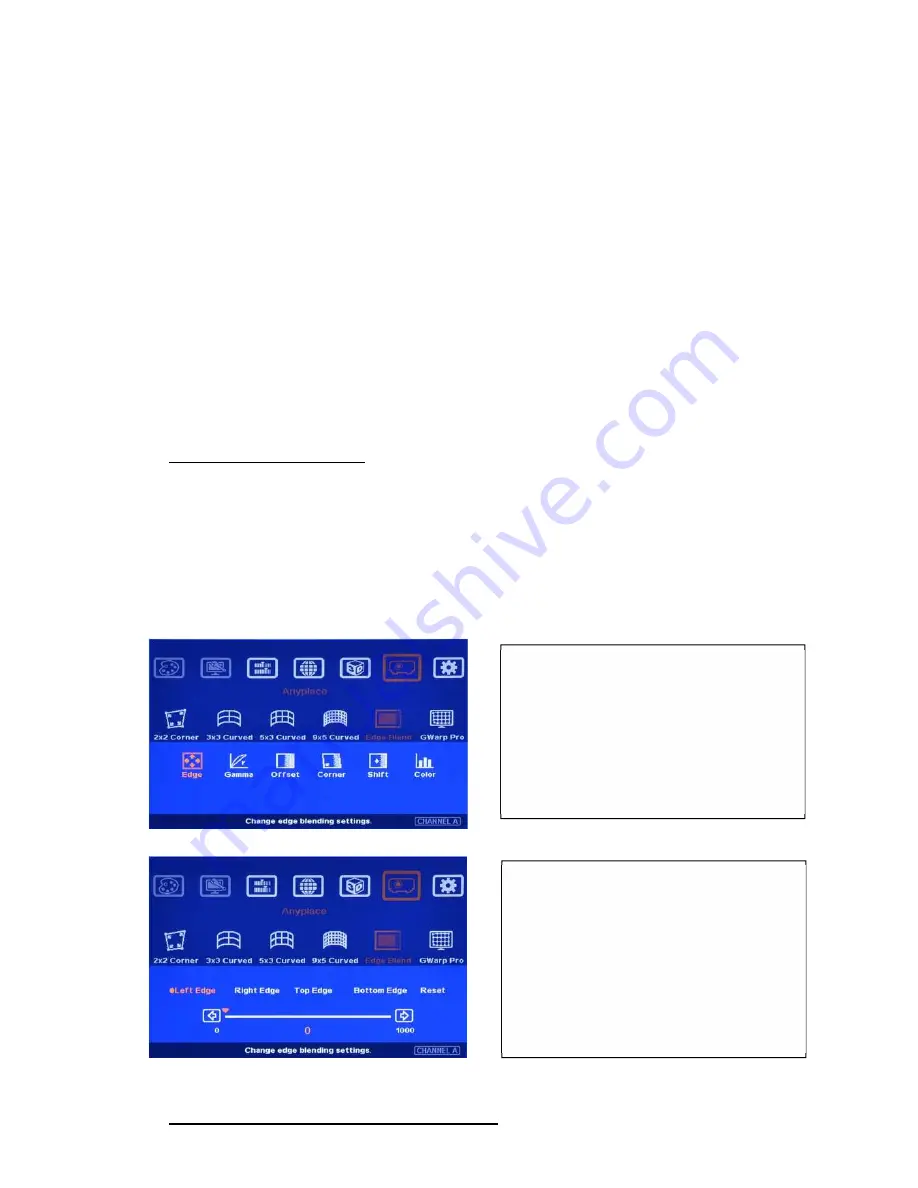
Sub-menu under [Edge Blend] menu
[Edge]: select the right edge and set overlap pixels
[Gamma]: select correct gamma for overlapped area and [Offset] compensation area to
eliminate banding effect.
[Offset]: to do black level uplift in non-overlapped area to compensate light leakage in projectors.
[Corner]: to do precise [Offset] location alignment.
[Shift]: shift the location in edge blend area. In some case, it may help color fine-tune. [Shift] can
also do [Edge Mask] for non-overlap edges with black background.
[Color]: to do discrete color adjustment for individual projector.
12.5.1 [Edge] selection and settings
a.
[Edge] is to select the edge for edge blend and set overlapped pixel number.
b.
User can execute edge blending at any edge.
c.
Maximum edge blend pixels are 900. If over this number, please consider using image stack or
change aspect ratio in projector to shrink projection image. User can also reduce edge blending
area by geometry alignment in two vertical borders of edge blending area. Each projector shall
reduce the same pixels and maintain the same image size and scaling factor.
12.5.2 [Gamma]: Color correction in edge blending area
Color indicating lines will appear when
set edge blending pixels.
User only needs to adjust the color
indicating lines to match together (green
to green, red to red). There is no need to
calculate the overlapped pixels.
User needs to select correct edge for edge
blending.
For 3 projector edge blending as example:
To select [Left Edge] for RH projector
To select [Right Edge] for LH projector
To select both [Right Edge] & [Left
Edge] for center projector.


