Vi
suNet
XT
9
700
Seri
es
48
VisuNet XT 9700 Series
Field Maintenance and Repair
7.2.2
DC Power Supply Removal and Replacement
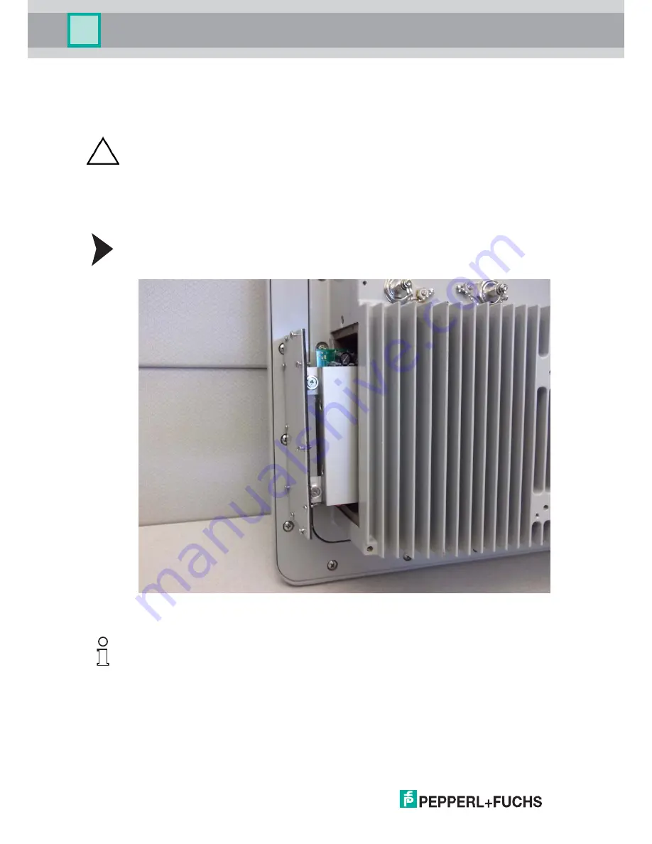
Remove the power supply by performing the following steps.
1. Loosen the ten (10) #4-40 captive screws securing the power supply cover plate in place.
See Figure 7.8.
Figure 7.8Power Supply Cover Plate
2. Pull the power supply straight out of the housing.
Caution!
Remove power to the unit before beginning this procedure.
This procedure must be performed in a clean, non-hazardous environment free of dust
and contaminants. Make sure no liquids or dust particles penetrate the unit.
It is highly recommended that the service technician be properly grounded using a
grounding strap during this procedure.
Note!
The power supply is attached to a mounting bracket, and the mounting bracket is attached to
the inside surface of the cover plate.
Summary of Contents for XT-9700
Page 1: ...VisuNet XT 9700 Series PROCESS AUTOMATION USER MANUAL ...
Page 6: ...4 VisuNet XT 9700 Series THIS PAGE IS INTENTIONALLY LEFT BLANK ...
Page 10: ...VisuNet XT 9700 SEries 8 VisuNet XT 9700 Series Safety THIS PAGE IS INTENTIONALLY LEFT BLANK ...
Page 71: ...VisuNet XT 9700 Series Appendix VisuNet XT 9700 Series 69 ...
Page 72: ...VisuNet XT 9700 Series Appendix VisuNet XT 9700 Series 70 ...
Page 73: ...VisuNet XT 9700 Series Appendix VisuNet XT 9700 Series 71 ...
Page 74: ...VisuNet XT 9700 Series Appendix VisuNet XT 9700 Series 72 ...
Page 75: ...VisuNet XT 9700 Series Appendix VisuNet XT 9700 Series 73 ...
Page 76: ...VisuNet XT 9700 Series 74 VisuNet XT 9700 Series Appendix ...
Page 77: ...VisuNet XT 9700 Series 75 VisuNet XT 9700 Series Appendix ...
Page 78: ...VisuNet XT 9700 Series 76 VisuNet XT 9700 Series Appendix ...


