VisuNet XT 9700 Series
Connectors and Cabling
Vi
suNet
XT
9
700
Seri
es
29
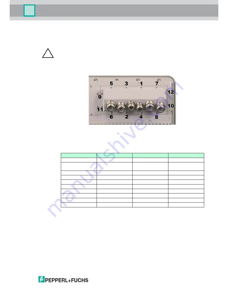
2. Place the junction box on the housing and tighten the captive screws to 0.8 Nm (7 in.-lb.)
in an inside-to-outside crisscross pattern using the incremental order shown in
Figure 5.3
to ensure the plate seals correctly.
Figure 5.3 Junction Box Incremental Screw Tightening Order
5.2
I/O Plates
Table 5.1
lists all the possible available I/O connections.
Table 5.1 Available I/O Connections
Figure 5.4
shows I/O plate details and connector locations.
Caution!
Do not use thread locker products on any screw thread.
Do not over-tighten the screws.
Failure to install the cover plate in the manner described may result in loss of enclosure
protection.
I/O
Quantity
Form Factor
Rating
VGA
1
15 pin D-SUB
USB 2.0
2
Terminal Block
Isolated
(Non-Incendive optional)
Serial Ports (RS232)
1
Terminal Block
Isolated
Serial Ports (RS485)
1
Terminal Block
Isolated
Ethernet CAT5
2
RJ45
Ethernet Fiber
1 (Duplex)
ST Connector
Power
1
Terminal Block
Audio I/O
1 of each
Terminal Block
Digial I/O
1 of each
Terminal Block
Wireless Antenna
2
SMA Coax
Summary of Contents for XT-9700
Page 1: ...VisuNet XT 9700 Series PROCESS AUTOMATION USER MANUAL ...
Page 6: ...4 VisuNet XT 9700 Series THIS PAGE IS INTENTIONALLY LEFT BLANK ...
Page 10: ...VisuNet XT 9700 SEries 8 VisuNet XT 9700 Series Safety THIS PAGE IS INTENTIONALLY LEFT BLANK ...
Page 71: ...VisuNet XT 9700 Series Appendix VisuNet XT 9700 Series 69 ...
Page 72: ...VisuNet XT 9700 Series Appendix VisuNet XT 9700 Series 70 ...
Page 73: ...VisuNet XT 9700 Series Appendix VisuNet XT 9700 Series 71 ...
Page 74: ...VisuNet XT 9700 Series Appendix VisuNet XT 9700 Series 72 ...
Page 75: ...VisuNet XT 9700 Series Appendix VisuNet XT 9700 Series 73 ...
Page 76: ...VisuNet XT 9700 Series 74 VisuNet XT 9700 Series Appendix ...
Page 77: ...VisuNet XT 9700 Series 75 VisuNet XT 9700 Series Appendix ...
Page 78: ...VisuNet XT 9700 Series 76 VisuNet XT 9700 Series Appendix ...


