background image

9

Operating Instructions

The easiest way to make sure that an efficient flame is achieved is to understand the characteristics of 

the fire. 

Figure 7: Efficient Flame.

G

UIDELINES

 F

OR

 F

INE

-T

UNING

 F

OR

 F

UEL

 Q

UALITY

:

Due to fuel quality the slider damper and control board trims may need to be fine-tuned.

1. If the unit builds up on all settings, the slider damper rod should be pulled out in small increments to 

give the unit more air.

2. If the unit has excesses ash build-up in the liner on the lower feed settings, the Combustion Blower 

Trim should be increased one setting at a time until the problem improves (Factory Setting is #2).

3. If the fire is going out on low because the airflow is too great, the Combustion Blower Trim can be 

lowered to the #1 setting.

4. If the stove has excesses ash build-up in the liner on the higher settings the Feed Rate Trim should be 

trimmed down a setting at a time until the problem improves (Factory setting is #4).

5. If you need more heat and the fuel has long pellets, the majority are over 1” (2.5cm) in length, the 

Feed Rate Trim can be moved up to the #5 setting. NOTE: Only do this if the fuel burns without 

building up.

•  A tall, lazy flame with dark orange tips requires more air – Open 

slider (pull out) slightly.

•  A  short,  brisk  flame,  like  a  blowtorch,  has  too  much  air  –  Close 

slider (push in) slightly.

•  If  the  flame  is  in  the  middle  of  these  two  characteristics  with  a 

bright yellow/orange, active flame with no black tips then the air is 

set for proper operation, refer to Figure 7.

The combustion exhaust blower is a variable speed blower controlled 

by  the  heat  output  button.  This  blower  will  decrease  the  vacuum 

pressure inside the stove, adjusting the air to fuel ratio. 

SPECIAL NOTES:


Pellet quality is a major factor in how the Pellet stove will operate. If 

the pellets have a high moisture content or ash content the fire will 

be less efficient and has a higher possibility of the fire building up and 

creating clinkers (hard ash build-up).

Summary of Contents for VF 100A

Page 1: ...LET STOVE VF 100A OWNER S MANUAL Freestanding Fireplace Insert PLEASE READ THIS ENTIRE MANUAL BEFORE INSTALLATION AND USE OF THIS PELLET BURNING ROOM HEATER FAILURE TO FOLLOW THESE INSTRUCTIONS COULD...

Page 2: ...15 Outside Fresh Air Connection 16 Exhaust And Fresh Air Intake Locations 16 Vent Termination Requirements 17 Mobile Home Installation Freestanding 18 Corner Through Wall Installation Freestanding 18...

Page 3: ...4 to 5 16 diameter 1 2 11 2 long maximum Ash Content 1 maximum Premium grade 3 maximum Standard grade Moisture Content 8 maximum Heat Content approximately 8200 Btu per pound minimum ASH The ash cont...

Page 4: ...inor soot or creosote may accumulate when the stove is operated under incorrect conditions such as an extremely rich burn black tipped lazy orange flames SAFETY WARNINGS AND RECOMMENDATIONS Caution Do...

Page 5: ...moke detectors should be installed and maintained in the structure when installing and operating a pellet burning appliance OPERATION The ash pan and door must be closed securely for proper and safe o...

Page 6: ...F100 Freestanding DIMENSIONS INSERT Regular Panel 40 1016mm Oversized Panel 46 1158mm 22 3 4 579mm 12 5 8 322mm 23 5 8 601mm Regular Panel 30 1 8 766mm Oversized Panel 32 7 8 835mm 22 3 4 579mm 22 559...

Page 7: ...except for the one that shows the current setting the default setting is the number 2 light To adjust the setting hold the Combustion Blower Trim button down and press the Heat Level up or down butto...

Page 8: ...TRIM COMBUSTION BLOWER TRIM HEAT LEVEL AUTO OFF HIGH LOW MANUAL AUGER C 11625 MODE 1 2 3 4 5 6 8 7 9 ROOM AIR FAN ON OFF ON OFF FEED RATE TRIM COMBUSTION BLOWER TRIM HEAT LEVEL AUTO OFF HIGH LOW MANUA...

Page 9: ...ting at a time until the problem improves Factory setting is 4 5 If you need more heat and the fuel has long pellets the majority are over 1 2 5cm in length the Feed Rate Trim can be moved up to the 5...

Page 10: ...ing a metal scraper remove material that has accumulated or is clogging the liner s holes Then dispose of the scrapped ashes from the liner and from inside the burn pot Place the burn pot back into th...

Page 11: ...let stove insert s ash pan is located behind the lower grill Routine Cleaning and Maintenance Figure 9 VF100 Heat exchanger rod Heat exchange tube cleaner rod HEAT EXCHANGER TUBES 2 3 days The handle...

Page 12: ...right side of the stove will require lubrication The convection motor has two lubrication holes on it Use two drops of SAE 20 light oil to lubricate every six months Excess oil may damage the motor T...

Page 13: ...be obtained from a ventilated crawlspace 8 The power cord is 8 feet 2 43 m long and may require a grounded extension cord to reach the nearest electrical outlet AUTOMATIC SAFETY FEATURES OF YOUR PELLE...

Page 14: ...e Fireplace Insert model come with a pedestal that has to be attached prior to installation 1 Remove the unit from the box 2 Remove the pedestal from the hopper 3 Place the unit on its back on the pal...

Page 15: ...in front of the appliance 301 2 775 mm Side wall to unit 6 inches 15 cm Back wall to unit 1 inches 2 5 cm Corner to unit 1 inches 2 5 cm Door front to edge of floor protection 6 inches 15 cm NOTE Thes...

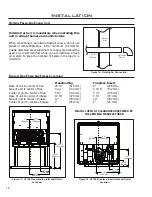
Page 16: ...NS Freestanding Fireplace Insert Base of unit to center of flue 20 1 4 515 mm 9 228 mm Side of unit to center of flue 5 3 16 132 mm 5 3 16 132 mm Center of unit to center of flue 5 3 4 146 mm 5 3 4 14...

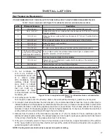
Page 17: ...PELLET STOVE BE INSTALLED BY AN AUTHORIZED DEALER INSTALLER Figure 19 Use in conjunction with Table 1 for allowable exterior vent termination locations Table 1 Use in conjunction with Figure 19 for a...

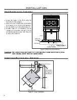
Page 18: ...heater to the floor using the two holes in the pedestal Ensure the unit is electrically grounded to the chassis of your home permanently Do not install in a room people sleep in Outside fresh air is...

Page 19: ...iance 15 37 5 cm away from the wall If the stove is to be set on a hearth pad set the unit on it 4 Locate the center of the exhaust pipe on the stove Extend that line to the wall Once you have located...

Page 20: ...y be required if a proper burn cannot be maintained after the stove has been tested and the airflow set This is due to the back pressure in the exhaust caused by airflow around the structure Follow ve...

Page 21: ...he fresh air intake pipe 6 Install the tee with clean out 7 Install the pellet vent upward from there When you reach the ceiling make sure that the vent goes through the ceiling fire stop Maintain a 3...

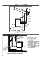
Page 22: ...de Vertical Installation Refer to Figures 28 and 29 1 Install the hearth pad 2 Lock fireplace damper in the open position 3 Install a positive flue connector at the fireplace dampers 4 Connect a tee o...

Page 23: ...edestal When installing this unit ensure that the pedestal is removed from the inside of the hopper and installed on the bottom of the unit see PEDESTAL INSTALLATION Assemble surround panel see ASSEMB...

Page 24: ...ireplace insert to the top of the chimney The liner must conform to type 3 requirements of CAN ULC S635 6 Recommended Install fresh air intake either through the back of the fireplace or through the p...

Page 25: ...aceplate complies with the requirement 6 Alteration of the fireplace in any manner is not permitted with the following exceptions external trim pieces which do not effect the operation of the fireplac...

Page 26: ...er and the screw heads are to face out With the bracket in place and the top and a side trim snug together use a flat head screwdriver to turn the two 2 screws in the bracket to tighten it into the tr...

Page 27: ...ee OPERATION INSTRUCTION SLIDER DAMPER SET UP Installation THERMOSTAT INSTALLATION Remove jumper wire and install thermostat wires here Figure 38 Thermostat wire placement 1 Install the wall thermosta...

Page 28: ...placed in the ON OFF thermostat mode then turn the thermostat up to call for heat Check the Heat Level Indicator If the 2 light is flashing see the 2 light is flashing Check the fuse on the circuit b...

Page 29: ...gnitor Everything else in the stove operates but the ignitor will not light the pellets Check the burn pot liner placement Make sure the burn pot liner is up tight and square to the ignitor tube by pu...

Page 30: ...acts have opened for more than 15 sec Pinch break or blockage in Vacuum Hose Check hose for pinch points or damage replace or re route as required Blow out Vacuum Hose Blocked Hose Barb on Exhaust Cha...

Page 31: ...Yellow Yellow Grey Grey Grey Grey Purple Purple Blue 115V Black 220V Brown Black Black Black Blue Black Armor Cable Supplied Vacuum Switch Combustion Blower Optional Exterior Exhaust Blower Power Cor...

Page 32: ...erature Sensor 120 F 49 C Ceramic EF 015 6 High Limit Temperature Sensor 200 F 93 C Manual Reset EF 016 7 Vacuum Switch 115V EF 017 Silicone Hose EF 018 Aluminum Hose Barb EF 019 8 Ignition Burn Pot E...

Page 33: ...ide EF 134 Ignitor Tube Only EF 140 Freestanding Hopper Lid Hinge EF 141 25 Freestanding Hopper Side Rail Left Right EF 143 26 Insert Hopper Side Rail Left Right EF 145 Pellet Stove Cleaning Brush EF...

Page 34: ...Control Panel Door 20 040 Control Panel Touch Latch 50 323 40 Combustion Blower Exhaust Tube 50 327 Combustion Blower 115V 50 473 41 Stainless Steel Burn Pot Liner Standard 50 474 Flush Handle for Hop...

Page 35: ...35 Parts Diagram Components...

Page 36: ...Parts Diagram Steel 36...

Page 37: ...rtain restrictions and exclusions apply to this warranty Limited Two 2 Year Warranty Under this warranty Sherwood Industries Ltd covers Ignitor Auger Motor Circuit Board Timers Temp Sensors Blowers Va...

Page 38: ...y the Limited Warranty on this stove If unsure as to the extent of this Limited Warranty contact your authorized VistaFlame dealer before installation 10 Sherwood Industries Ltd will not be responsibl...

Page 39: ...per our warranty service fee reimbursement schedule Labour rates are set per component and as such total labour costs may not be covered 27 Sherwood Industries Ltd is not liable for freight or labour...

Page 40: ...______________________ PHONE ___________________________________ MODEL ___________________________________ SERIAL NUMBER ___________________________ DATE OF PURCHASE _____________ dd mm yyyy DATE OF I...

Reviews: