Vista VP-HDA20IR-SMW Installation Manual Download Page 3

Before You Begin 

Read these instructions before installing or operating this product. 

Note:

 This installation should be made by a qualified service person and should conform to local codes.  

This manual provides installation and operation information.  To use this document, you must have the following 
minimum qualifications: 

• A basic knowledge of CCTV systems and components 

• A basic knowledge of electrical wiring, low-voltage electrical connections and IP networking/infrastructure  

Intended use 

Only use this product for its designated purpose; refer to the product specification and user documentation. 

Using the camera in continuous motion applications e.g. Auto Scan, Tour, or Pattern functions with Auto Focus 
(Auto (AF) will reduce the warranty to 6 months.   

Customer Support 

For  assistance  in  installing,  operating,  maintaining  and  troubleshooting  this  product  refer  to  this  document  and 
any  other  documentation  provided.    If  you  still  have  questions,  please  contact  Norbain  Technical  Support  and 
Sales: 

Norbain SD, 210 Wharfedale Road, Winnersh Triangle, Wokingham, Berkshire RG41 5TP, England.  

UK +44 (0) 118 912 5000 / Vista Technical S44 (0) 118 912 5125  

Note:

 You should be at the equipment and ready with details before calling Technical Support. 


Conventions Used in this Manual 
Boldface

 or button icons highlight command entries.  The following 

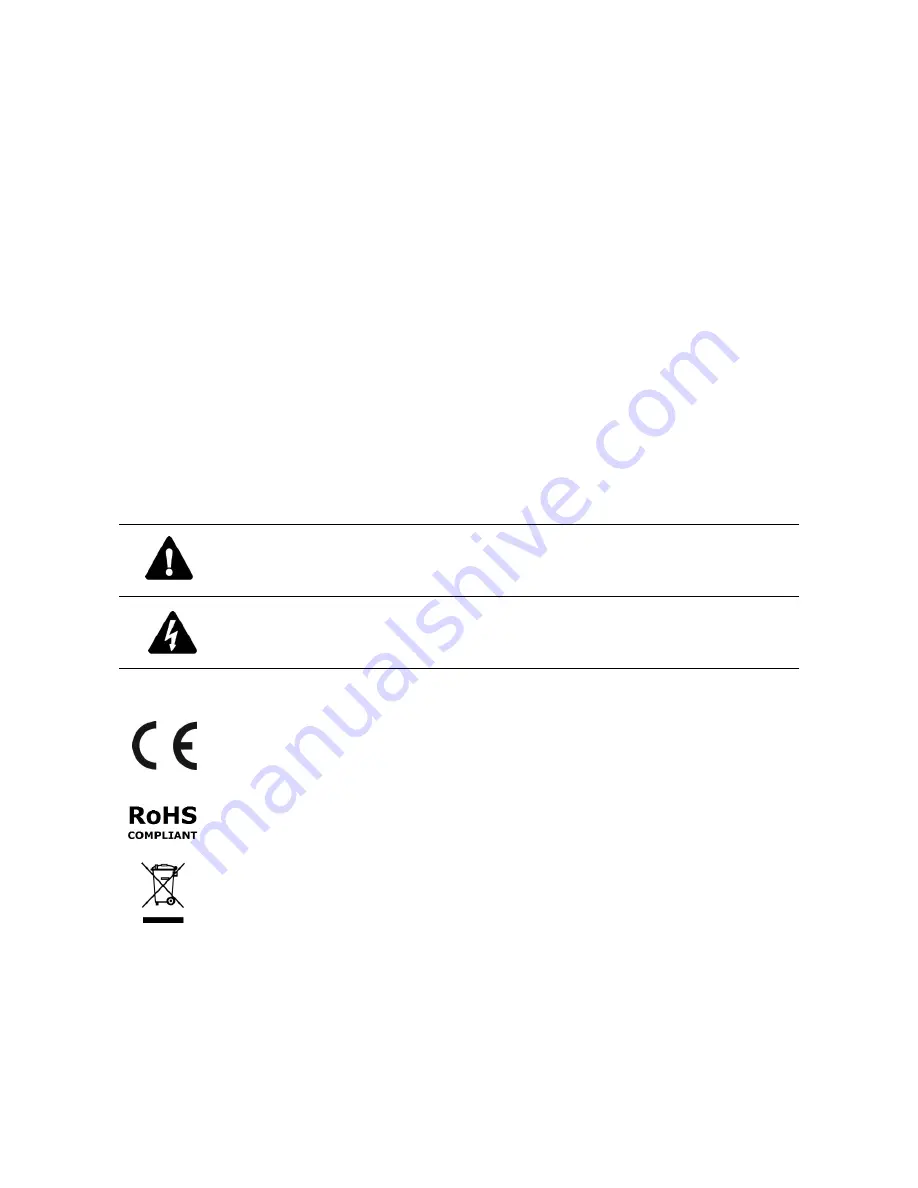
WARNING,


CAUTION

 and 

Note

 statements 

identify potential hazards that can occur if the equipment is not handled properly: 


* WARNING:  

Improper use of this equipment can cause severe bodily injury or equipment damage. 


* CAUTION: 


Improper use of this equipment can cause equipment damage. 


Note:

 Notes contain important information about a product or procedure.


This apparatus is manufactured to comply with the radio interference. 
A Declaration of Conformity in accordance with the following EU standards has been made. The 
manufacturer declares that the product supplied with this document is compliant the provisions of 
the  EMC  Directive  2004/108/EC,  the  CE  Marking  Directive  93/68  EEC  and  all  associated 
amendments. 

All lead-free products offered by the company comply with the requirements of the European law 
on  the  Restriction  of  Hazardous  Substances  (RoHS)  directive:  2011/65/EU,  which  means  our 
manufacture  processes  and  products  are  st

rictly  “lead-free”  and  without  the  hazardous 

substances cited in the directive.  

The crossed-out wheeled bin mark symbolizes that within the European Union the product must 
be  collected  separately  at  the  product  end-of-life.    This  applies  to  your  product  and  any 
peripherals  marked  with  this  symbol.    Do  not  dispose  of  these  products  as  unsorted  municipal 
waste. 


* This symbol indicates electrical warnings and cautions. 

** This symbol indicates general warnings and cautions. 

NORBAIN  SD  reserves  the  right  to  make  changes  to  the  product  and  specification  of  the  product  from  time  to 
time without prior notice. 

WARNINGS AND CAUTIONS: 

To reduce the risk of fire or electric shock, do not insert any metallic objects through the ventilation grills or other 
openings on the equipment. 

Summary of Contents for VP-HDA20IR-SMW

Page 1: ...VP HDA20IR SMW Manual V1 0 Installation Manual VP HDA20IR SMW Please read this manual thoroughly before use and keep it handy for future reference...

Page 2: ...2...

Page 3: ...if the equipment is not handled properly WARNING Improper use of this equipment can cause severe bodily injury or equipment damage CAUTION Improper use of this equipment can cause equipment damage No...

Page 4: ...the obsolete outlet 9 Protect the power cord from being walked on or pinched particularly at plugs convenience receptacles and the point where they exit from the apparatus 10 Only use attachments acc...

Page 5: ...ration Error Bookmark not defined 3 1 Dome Camera Selection Error Bookmark not defined 3 2 Accessing the On Screen Menu Error Bookmark not defined 3 3 How to control the On Screen Menu Error Bookmark...

Page 6: ...ector and the random mode and the endless Auto Pan with 13 speed steps 8 Patterns up to 500 seconds and 16 Privacy Zones 4 Alarm inputs 2 Alarm outputs 5VTTL Variable speed from 0 1 sec to 380 sec Thr...

Page 7: ...contains the following Dome Camera 1 Instruction Manual This Document 1 Template Sheet 1 Mounting Bracket 1 Safety Lanyard 1 Accessory Kit 1 1 Mounting screws PH6 x 35 0 4 2 Plastic anchors 4 3 O Ring...

Page 8: ...be applied to seal the housing to secure waterproofing CAUTION Please reset the camera after 30 minutes when installing it in situations colder than 10 C 2 2 1 Locking the Dome Camera 1 Make screw hol...

Page 9: ...he tab of the mounting bracket into the locking slot Screws A should not be too tight or too loose when the dome is in the locked position After setting the proper positions of screws A remove the mou...

Page 10: ...BLOCK A1 ALARM INPUT 1 A2 ALARM INPUT 2 G GND 4 3 PIN TERMINAL BLOCK A3 ALARM INPUT 3 A4 ALARM INPUT 4 G GND 5 3 PIN TERMINAL BLOCK AO1 ALARM OUTPUT 1 AO2 ALARM OUTPUT 2 G GND 6 BNC BLACK HD OUTPUT 7...

Page 11: ...type with D2 in S1 S1 D1 Video Signal S1 D2 Video Type OFF HD TVI Output OFF NTSC ON AHD Output ON PAL You can set coaxitron protocol with D3 and D4 in S1 S1 D3 S1 D4 HD TVI Output AHD Output OFF OFF...

Page 12: ...nput 1 2 3 4 You can use external devices to signal the dome camera to react on events Mechanical or electrical switches can be wired to the A1 A2 A3 A4 Alarm Input 1 2 3 4 and G Ground connectors See...

Page 13: ...ower to the dome camera The dome camera will start a configuration sequence OSD Position 001 AF AE EMPTY DATA ALARM 1 DOMEID 0001 360 0 090 0 INFORMATION DISPLAY CAMERA TITLE ID PAN TILT ANGLE FUNCTIO...

Page 14: ...the On screen menu utility on your monitor by pressing the MENU key on the keyboard or DVR the following On screen menu utility will appear DOME MENU AUTO SCAN PRESET TOUR PATTERN PRIVACY ZONE CAMERA...

Page 15: ...UAL Follow these steps to program Auto Scan 1 Press the MENU key to display the main menu on the monitor Scroll to Auto Scan and press the Right key 2 Select NUMBER and set the desired number by press...

Page 16: ...zoom position Press the IRIS Close key then the CONTROL disappears To adjust at the 0 1 degree interval press the Tele or Wide key at the pan field and the tilt field To adjust at the one zoom interva...

Page 17: ...key to display the main menu on the monitor Scroll to Preset and press the Right key 2 Select the blank Preset position to be stored by pressing the Up Down Right or Left key 3 After selecting a blank...

Page 18: ...key Then the AE setup displays Refer to the AE SETUP in the camera setup 6 Set DWELL time 03 99 seconds 7 To select the next page of Presets scroll the page by pressing the Right or Left key on the f...

Page 19: ...key 5 To add a stored Preset press the Tele or Wide key then the stored Preset number displays 6 To place functions other than Preset press the IRIS Open key to scroll for Tour Pattern or Auto Scan r...

Page 20: ...n the Tour when the function key is not existed Move the cursor to a stored Preset position Pressing the IRIS Open key will change the Preset number to other function Auto Scan Pattern Tour or Preset...

Page 21: ...oll to Pattern and press the Right key to enter the Pattern menu 2 Select the desired Pattern to be programmed by pressing the Up or Down key If the Pattern is not 000 a Pattern has already been recor...

Page 22: ...e IRIS Open key then the privacy area menu displays Move the desired position Press the IRIS Close key then the CONTROL disappears To adjust the size press the Tele or Wide key Returns to the previous...

Page 23: ...nge IMAGE FLIP This function turns the video output from the camera upside down and reverses it horizontally This option is helpful to install in the opposite side PRESET FREEZE ON the image is frozen...

Page 24: ...nt lamps OUTDOOR Outdoor white balance mode MANAUL Manual mode you can change R and B Gain manually R GAIN 0 255 B GAIN 0 255 R GAIN B GAIN modes are controllable only in MANUAL Mode AE CONTROL AE SET...

Page 25: ...TE When ON BLC will be disabled WDR WEIGHT LOW MID HIGH BLC OFF ON NOTE When ON WDR will be disabled HLC OFF ON HLC LEVEL 0 20 HLC COLOR BLACK WHITE YELLOW CYAN GREEN MAGENTA RED BLUE DEFOG OFF ON CAM...

Page 26: ...LOR Color mode NOTE AUTO in D N mode is not applied in MANUAL mode of AE Control D N LEVEL LOW MID HIGH IR BRIGHT Specify the bright of the IR illuminator 1 20 IR ON LEVEL Specify the illumination lev...

Page 27: ...D 1 3999 PROTOCOL AUTO F2 F2E PELCO PD BAUDRATE 2400 4800 9600 19200 38400 bps PARITY NONE EVEN ODD TERMINATION RS 485 OFF ON The device which is connected at end of line whether it is a dome camera o...

Page 28: ...arm message will disappear from the screen after programmed hold time when alarm input is deactivated DWELL Means the dwell time during multiple alarms 03 to 99 seconds ALARM OUT SETUP OUT1 ALARM OUT2...

Page 29: ...amera automatically goes to Tour Pattern Auto Scan or Preset after the keyboard or DVR has been idle for a specified amount of time For example if the controller is idle for 120 seconds the camera goe...

Page 30: ...MIT 5 10 This option is designed to limit the view angle as there is some obstruction in zooming out on specific areas of the tilt angle PANNING RANGE When the dome camera is installed near a wall pan...

Page 31: ...ected by this function Offset is still valid after origin set OSD DISPLAY OSD DISPLAY SETUP LANQUAGE ENGLISH TITLE DOMEID DOME OSD ON FOCUS EXPOSURE OFF COLOR YELLOW SAVE AND EXIT ESC TO CANCEL LANGUA...

Page 32: ...L ONE PUSH This option set the default mode of the focus when you save the Preset MOTOR SETUP Motor Setup menu provides the pan and tilt speed of a camera User can set the desired speed with pressing...

Page 33: ...fault password is 555555 When the password enable is on the input password window displays to enter the menu At this time move the cursor to the desired character with the controller and press the IRI...

Page 34: ...xecute the function you should save the function PRESET PATTERN TOUR and SCAN first HOME Select HOME and press the IRIS Open key The dome camera goes to the default position that it returns to after a...

Page 35: ...x xxxx ROM VERSION Vx xxxxxx PROTOCOL xxxx BAUDRATE 9600 NONE EXIT ESC TO EXIT The system information provides essential information about the dome camera if service is required This screen displays t...

Page 36: ...Effect Flip DIS Defog Shutter Speed 25 30fps Auto 1 30 000 x8 sec Manual 50 60fps Auto 1 50 000 x8 sec Manual IR Illuminator 4 IR LEDs VIDEO Resolution HD TVI 1080p 25 30fps 720p 25 30 50 60fps AHD 1...

Page 37: ...densing Operating Temperature 20 C 50 C Power Supply 12VDC Power Consumption 1 5A 18W 12VDC Dimensions See dimension drawing Net Weight Approx 2 8kg Ingress Protection IP66 Specifications are subject...

Page 38: ...lution No video Verify that power is connected to all pieces of equipment in the system Verify that the power switches are in the ON position Check the video connections Poor video quality Check that...

Page 39: ...34 Vista 210 Wharfedale Road Winnersh Triangle Wokingham Berkshire RG41 5TP Subject to change without notice Version 1 50304269A...

Reviews: