


47
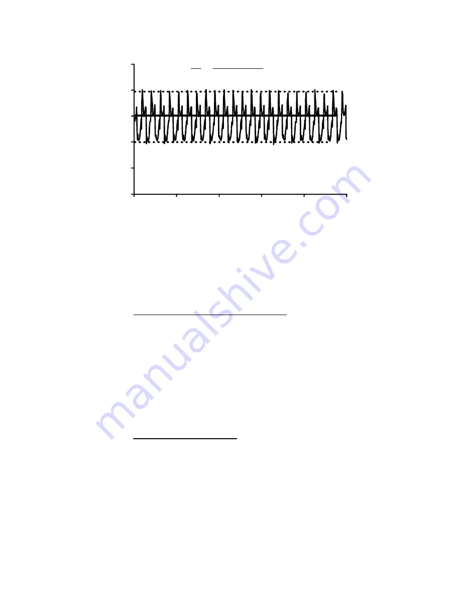
Inlet Pressure (mv)
360
366
372
378
384
390
0.00
1.00
2.00
3.00
4.00
5.00
Retention Volume (ml)
(
)
S
N
=
−
=
378
384 372
315
.
Figure 20 Measurement of Pump Pulsation from the IP Signal/Noise
In most (but not all) cases, the pump pulsation is regular, so one can measure the noise using
the peak-to-peak method as shown.
Guideline: The IP signal/noise ratio will need to be greater than 200 in order to obtain
optimum
S/N
on the DP signal.
C.3.d Checking Background Light Scattering
From time to time the background scattering should be checked following this procedure:
Flush out the detector with THF. Turn the laser off. Zero the scattered signal. Turn the laser
back on and read the background signal for both the RALLS and the LALLS. The background
signal for the LALLS should be around 15% less than the RALLS signal. Run a fresh
Polystyrene standard of 90,000 Da. Calibrate both detector signals. The LS calibration
constant for the LALLS detector should be 50% less that the RALLS detector. If either of these
values are significantly different, then you may have a contaminated optics system. Please
contact the Viscotek Technical Service and Support department for further instructions.
C.3.e Standard Sample Analysis
Periodically it is a good idea to check the performance of the detector by running a
polymer standard sample and comparing it to that obtained upon installation. The
recommended standard for organic solvent use is one of the narrow MWD polystyrene
standards. For aqueous solvent use, one of the narrow MWD polyethylene oxide or
polyethylene glycol standards are recommended. Choose a standard somewhere in the
molecular weight range of 20K - 100K. Before running the standard, check the baseline
performance as described under sections C.3.a-c. If the detector baselines are within
specifications, run the standard sample and calculate the intrinsic viscosity. Intrinsic viscosities
of the standards should follow the Mark-Houwink relationships below.