4 – 17
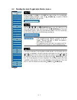
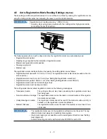
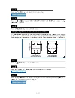
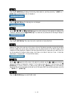
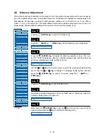
Measure the offset of the crosshairs in the X-axis, and enter the distance adjustment. Using the already
plotted crosshairs as the point of reference, enter the actual amount of the offset between these crosshairs
and the crosshairs that were plotted on top of them after the already plotted crosshairs were read by the
sensor. (For example, for the figure at the above right, since there is an offset in both the –X and –Y direc-
tions, enter the [X= –**mm] and [Y= –**mm] corrective values.)
Move the cursor to the digit to be entered using the
or
key, use the
or
key to increase or
decrease the values (or display/don’t display “-” for the space to the right of “=”), and then press the
(ENTER) key to confirm. If there is no offset, simply press the
(ENTER) key. The Y-axis distance-
adjustment input is then displayed and should be set in the same way. To cancel, press the
(NEXT) or
(PREV.) key.
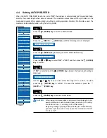
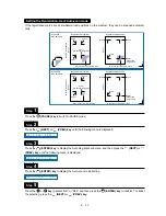
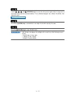
Press the
(PAUSE) key to cancel PAUSE mode.
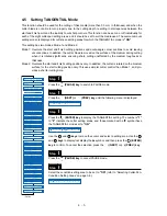
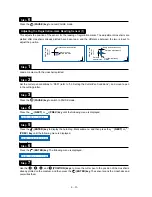
This adjusts the position of the sensor for reading the registration marks by plotting crosshairs and then
reading them. First set both cutter pen conditions 1 and 2 to the same pen. Crosshairs are first plotted
using conditions 1 and read by the sensor. A second set of adjustment crosshairs is plotted using condi-
tions 2. The difference between the two is input to adjust the position.
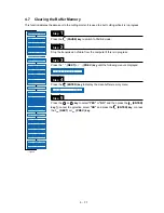
Load a medium into the cutting plotter.
Set both cutter pen conditions 1 and 2 to the same “Pen” (refer to “3.3 Setting the Cutter-Pen Conditions”),
and load a pen in the cutting plotter.
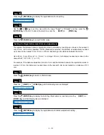
Press the
(PAUSE) key to switch to PAUSE mode.
Press the
(NEXT) or
(PREV.) key until the following menu is displayed.
Step
8
Step
9
Step
10
Adjusting the Registration-mark Reading Sensor (2)
Step
1
Step
2
Step
3
Step
4
A D J X = 0 . 0
Medium f
eed
direction
Crosshairs first plotted
Adjustment crosshairs
Distance adjustment Y
Distance
adjustment X
X
Y
A U T O R E G . M A R K
Summary of Contents for Qe60
Page 1: ...Vinyl Express Qe60 USER S MANUAL MANUAL NO VEXQe06 UM 151 CUTTING PLOTTER Signwarehouse com ...
Page 2: ......
Page 6: ...iv ...
Page 28: ...2 14 ...
Page 42: ...3 14 ...
Page 94: ...4 52 ...
Page 100: ...5 6 ...
Page 110: ...A 4 Appendix C External Dimensions Units mm Dimensional accuracy 5 mm 851 585 1004 ...
Page 112: ...A 6 ...

