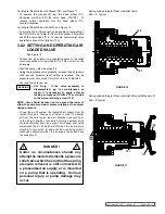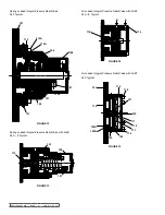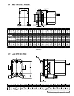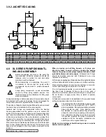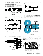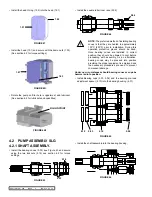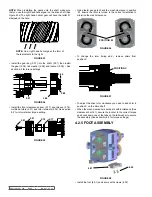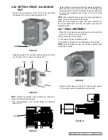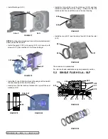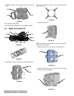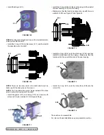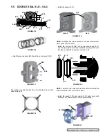
fIGURE 69
2.01
2.02 / 2.03
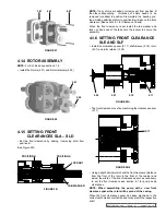
fIGURE 70
3.01
1.04
fIGURE 68
fIGURE 67
3.01
7.03
4.03
4.04
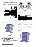
fIGURE 64
4.01
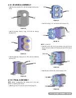
fIGURE 65
4.02
fIGURE 66
4.08
4.04
SECTION TSM 288
ISSUE
A
PAGE 22 OF 36
• Install the rotors (2.01) and rotor retainer O-ring (2.03) and
secure with rotor retainers (2.02) (See section 6.2 for torque
settings)
• Install the head studs (1.04) into the casing (3.01)
• Install the guard (7.03) onto the rear of the casing (3.01)
• Install the casing (3.01) and secure with screws (4.07
4.2.8 GEaRbOX assEMblY
• Install the rear lip-seal (4.03) into the bearing housing cover
(4.04)
• Install the bearing housing O-ring (4.02) into the bearing
housing (4.01). See Figure 65.
• Install the bearing housing cover (4.04) and the retaining
screws (4.08)
NOTE:
Before re-assembling the casing refer to the seal
section for instructions


