Viking pump SLAL Technical & Service Manual Download Page 8

SECTION TSM 288

ISSUE

A

PAGE 8 OF  36

Integral pressure relief valves are normally used to protect the 

pump from the effects of increases in system pressure caused, 

for  example,  by  a  restricted  or  closed  discharge  line.    In 

response to a pressure increase the valve opens and internally 

circulates the pumped media within the pump chamber.

When  the  valve  opens,  because  the  volume 

of  fluid  circulating  is  relatively  small,  the 

temperature  of  the  fluid  in  the  pump  chamber 

may  rise  if  the  pump  continues  to  operate  for 

an  extended  period.    In  severe  cases  this  may 

result  in  temperatures  in  excess  of  the  pumps 

operating limits or vaporisation of the fluid, both 

of which should be avoided.  For these reasons 

when  the  valve  is  activated  the  cause  of  the 

system pressure increase should be eliminated 

as  continuous  operation  of  the  pump  with  the 

valve open is not recommended and may cause 

severe damage to the pump.

If the pump on which the valve is installed  is to be installed 

in either a pressurized system or one incorporating a vessel 

under vacuum, the application of the valve should be referred 

to Viking Pump or their authorized distributor.
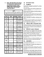
The selection, setting and application of integral relief valves 

is influenced by the viscosity and nature of the pumped media, 

the  pump  operating  speed  and  the  required  pressure  relief 

setting and mode of operation. For these reasons, and to cover 

the diverse range of products, the conditions under which they 

are  pumped,  and  application  demands,  it  is  not  practical  to 

factory set integral relief valves. The setting of the valve should 

be carried out on site under the proposed duty conditions for 

which the pump and valve were selected.

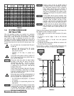
Before beginning the relief valve setting procedure 

the pump should be installed, (see section 3.4) 

with  a  pressure  gauge  in  the  discharge  line 

adjacent to the pump discharge port. 

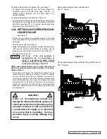
3.8.1 sETTING aNd OPERaTING 

sPRING lOadEd ValVEs

See Figures 10, 11, 12 and 13.

•  Remove cover (108).  For integral relief valve with manual 

lift,  see  Figure  11;  first  remove  nut  (129)  and  hand  wheel 

(111).  

•  Loosen nut (107) using a pry bar in the holes 

provided,  to  relieve  spring  compression.  For 

integral relief valve with airlift, see Figure 13, 

the  air  cylinder  must  be  exhausted  prior  to 

unscrewing the nut (107).

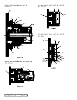
•  Start pump, refer to section 3.5.
•  Screw  in  nut  (107)  using  pry  bar  in  holes  provided  until 

required pressure relief setting is reached.

NOTE: Care should be taken not to exceed the 

lower of either the pumps maximum pressure 

rating or the system design pressure.

•  Reinstall cover (108). For integral relief valve with manual 

lift, see Figure 11; reinstall hand wheel (111) and nut (129).

•  The relief valve is now set.

3.6  sHUTdOWN PROCEdURE

After  shutting  the  pump  down  close  both  the 

suction and discharge valves and ensure that the 

necessary safety precautions are taken:

•  The  prime  mover  power  source  has  been 

isolated.

•  If installed, the pneumatically operated integral 

relief valve has been depressurized. 

•  If  installed,  flushed  product  seal  auxiliary 

services  have  been  isolated  and  de-

pressurized.

•  Pump head and piping have been drained and 

purged.

3.7   ROUTINE MaINTENaNCE

•  SL Series pumps are shipped fully lubricated with a lithium 

based  extreme  pressure  lubricant  suitable  for  sealed  for  

life units. 

•  For lubricant capacities refer to section 6.4.

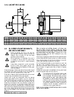
3.8  INTEGRal PREssURE RElIEf 

ValVEs

See Figures 10, 11, 12, 13, 14, and 15.

Most  models  in  the  SL  Series  series  can  be  supplied  with 

integral pressure relief valves with both spring and air loaded 

versions available. The function of the valves can be further 

enhanced with the option of manual or airlift override offering 

particular benefits where in-line cleaning is employed. Valves 

incorporating this option can be opened to regulate the volume 

of  the  cleaning  media  within  the  pump  chamber  thereby 

avoiding the need for manual cleaning or external by-pass.  
Where  the  pump  is  mounted  onto  a  portable  base  plate 

complete with motor and drive to be used as a mobile set, it 

is strongly recommended that a integral pressure relief valve 

is installed.
The SL Series integral pressure relief valves available 

include: 

Spring Loaded - see Figure 10, 11, 12, & 13.
Valve can be set to required pressure relief setting. 
Spring Loaded with Manual Lift - see Figure 11.
Valve can be set to required pressure relief setting.  Manual lift 

override can be used to open valve without disturbing pressure 

relief setting.
Spring loaded with airlift - see Figure 13.
Valve  can  be  set  to  required  pressure  relief  setting.    Airlift 

override, which operates on an air supply of up to 7 Bar (105 

psi) depending on pressure relief setting, can be used to open 

valve without disturbing pressure relief setting.
Air loaded with airlift - see Figure 14.
Valve, which operates on an air supply of up to 7 Bar (100 psi) 

for SLA - E, and 10 Bar (145 psi) for SLF, can be set to required 

pressure relief setting.  Airlift override, which operates on an air 

supply of up to 7 Bar (100 psi) for SLA - E and 10 Bar (145 psi) 

for SLF, depending on pressure relief setting, can be used to 

open valve without disturbing pressure relief setting.
Air  actuated  relief  valves  can  be  operated  remotely  and 

interfaced  with  other  elements  of  the  system  or  process 

control.

WaRNING

WaRNING

!

!

!

Summary of Contents for SLAL

Page 1: ...9 3 9 Rectangular Inlet 11 3 9 1 Jacketed Head 11 3 9 2 Jacketed Casing 12 4 0 SL Pump Dismantling and Assembly 12 4 1 Pump Assembly SLA SLF 13 4 1 1 Shaft Assembly 13 4 1 2 Rolling Torque Pre load 14 4 1 3 Casing Assembly 14 4 1 4 Rotor Assembly 15 4 1 5 Setting Front Clearances SLA SLD 15 4 1 6 Setting Front Clearance SLE and SLF 15 4 1 7 Foot Assembly 16 4 1 8 Timing Multilobe Rotors Only 16 4 ...

Page 2: ... to lubricate the seal faces Dry running can cause excessive heat and seal failure Pressure gauges sensors are recommended next to the pump suction and discharge connections to monitor pressures Caution must be taken when lifting the pump Suitable lifting devices should be used as appropriate Lifting eyes installed on the pump must only be used to lift the pump not pump with drive and or base plat...

Page 3: ... UK Ltd a subsidiary of Viking Pump Co a unit of the IDEX Corporation This manual includes all the necessary information for SL Series pumps and should be read prior to beginning installation operation or maintenance Should you require any additional information regarding the SL Series pumps contact Viking Pump or their local authorized distributor refer to section 2 2 When asking for assistance p...

Page 4: ... of appropriate cleaning solutions and brushes and new seals installed Refer to Section 5 for seal assembly instructions It is recommended that the exterior of the pump be cleaned periodically with a non aggressive non abrasive cleaning solution 2 5 Pump Model Designation The designations of pump models are as follows SLAS SLBS SLCS SLDS SLES SLFS SLGS SLAL SLBL SLCL SLDL SLEL SLFL SLGL This infor...

Page 5: ... head components For advice or assistance contact your Viking Pump distributor 2 8 Standard Pump Component Terms 3 0 General 3 1 SL Series Pumping Principle The pumping action of the rotary lobe pump principle is generated by the contra rotation of two pumping elements rotors within a chamber casing see Figure 6 The rotors are located on shafts that in turn are held within a bearing housing mounte...

Page 6: ... the following general guidelines should ensure the best possible suction condition is created Suction piping is at least the same diameter as the pump connections The length of suction piping is kept to the absolute minimum The minimum number of bends tees and pipework restrictions are used Calculations to determine system NPSHa are carried out for the worst condition see below Should advice on p...

Page 7: ...ings must always be incorporated and correctly aligned within the limits recommended by the coupling manufacturer To check coupling alignment rotate the shaft by at least one full revolution and ensure that the shaft rotates smoothly Couplings of a non flexible design must never be used Couplingsmustalwaysbeenclosedinasuitable guard to prevent contact with rotating parts that could result in perso...

Page 8: ...esign pressure Reinstall cover 108 For integral relief valve with manual lift see Figure 11 reinstall hand wheel 111 and nut 129 The relief valve is now set 3 6 Shutdown Procedure After shutting the pump down close both the suction and discharge valves and ensure that the necessary safety precautions are taken The prime mover power source has been isolated If installed the pneumatically operated i...

Page 9: ... Only If the valve assembly is disassembled e g for maintenance or repair it is necessary to apply a thread locking compound Loctite 270 or similar to the piston retaining screw 120 NOTE Care should be taken not to exceed the lower of either the pumps maximum pressure rating or the system design pressure To use the air lift system the regulated air supply must be routed through a change over valve...

Page 10: ...A 112 101 Figure 13 112 123 108 107 SECTION TSM 288 ISSUE A PAGE 10 OF 36 Air Loaded Integral Pressure Relief Valve with Airlift SLF Typical Air Loaded Integral Pressure Relief Valve with Airlift SLA E Typical Spring Loaded Integral Pressure Relief Valve SLF Typical Spring Loaded Integral Pressure Relief Valve with Airlift SLA E Typical ...

Page 11: ...11 75 11 75 6 7 7 9 9 10 12 10 10 15 15 20 J N A 20 2 17 2 29 2 21 2 35 2 25 3 40 3 36 3 60 3 48 3 82 3 78 3 131 3 19 8 16 8 28 8 20 8 34 8 24 7 39 7 35 7 59 7 47 7 81 7 77 7 130 7 K 2 4 4 4 4 4 4 4 4 4 4 4 4 4 L M6 M6 M8 M8 M8 M8 M10 M10 M12 M12 M16 M16 M16 M16 M 8 8 10 10 10 10 12 12 14 14 18 18 18 18 Q 45 45 60 60 66 5 66 5 89 89 117 117 132 132 149 149 V 3 3 3 3 3 3 3 3 3 3 3 3 3 3 X 134 137 1...

Page 12: ...ed into position 4 0 SL Series Pump Dismantl ing and Assembly Before undertaking any work on the pump the recommended shutdown procedure should be followed refer to section 3 6 and site safety practices must be observed While dismantling or assembling the pump it is essential to ensure that the pump and or components are secured to provide adequate stability Large pump components or sub assemblies...

Page 13: ... shaft 5 01 5 02 Install shafts assemblies into the bearing housing 4 01 Install rear bearing cone 5 04 into the bearing housing 4 01 Install bearing cups 5 03 5 04 into the bearing housing 4 01 To set the timing marks on the gears 5 06 place the gears next to each other and line up the keyways you can now punch three timing marks to show the correct alignment of the gears see Figure 22i NOTE When...

Page 14: ...housing See Figure 26 4 1 2 Rolling Torque Pre load Use a torque meter to check the rolling torque see section 6 2 for torque settings If the rolling torque is under over the required amount add remove shims to adjust the pre load to suit See section 6 2 Fasteners Torque Settings NOTE Rolling torque can only be set on new bearings with no sealing devices installed i e lip seals or O rings When che...

Page 15: ...earance See section 6 1 for Clearance Charts When the front clearance is set install the tab washer and lock nut bend one of the tabs onto the locknut to secure the assembly 4 1 6 Setting Front Clearance SLE and SLF Install the clearance spacer 5 17 shaft sleeve 5 18 rotor 2 01 and rotor retainer 2 02 The front clearance is set by machining the clearance spacer 5 17 Using a depth micrometer check ...

Page 16: ...ee section 6 2 and secure by knocking down one of the tabs on the tab washer Install the Front Lip seals 5 11 NOTE see lip seal fitting table for Instillation depths Section 6 3 4 1 7 Foot Assembly Install the foot 6 01 and secure with screws 6 02 4 1 8 Timing Multilobe Rotors Only Using feeler gauge to check the mesh clearance in position M ensure the rotor is turned in the correct orientation to...

Page 17: ...nto the bearing housing 4 01 Install the bearing housing cover 4 04 and the retaining screws 4 08 4 1 10 Final Assembly NOTE Before re assembling the casing refer to the seal section for assembly instructions Install the guard 7 03 onto the rear of the casing 3 01 Install the casing 3 01 and secure with screws 4 07 NOTE For the SLF Install the rotors 2 01 and rotor retainer O ring 2 03 and secure ...

Page 18: ...ent is employed and the necessary procedures are used to prevent component damage Under no circumstances should bearing cones or cups be hammered into position Install Bearing cups 5 03 5 04 and the bearing pre load adjustment spacer 4 10 into the bearing housing 4 01 Install the needle roller inner race 5 04 Install the shaft assembly into the bearing housing 4 2 Pump Assembly SLG 4 2 1 Shaft Ass...

Page 19: ...unt and will require adjustment To adjust the pre load modify the size of the bearing pre load adjustment spacer 4 10 NOTE When machining the spacer make sure small cuts are taken i e 0 02 mm 0 03 4 2 3 Final Pre load Assembly When the pre load is set remove the bearing pre load spacer 5 05 and install the front lip seals 5 11 refer to lip seal setting distances section 6 3 Install the gearbox O r...

Page 20: ...ecure the assembly See assembly 6 2 for torque settings 4 2 5 Foot Assembly Using feeler gauge to check the mesh clearance in position M ensure the rotor is turned in the correct orientation to minimize the mesh clearance Install the foot 6 01 and secure with screws 6 02 Install the front clearance spacer 5 17 seal sleeve 5 18 multilobe rotors 2 01 and rotor retainers 2 02 See section 6 2 for roto...

Page 21: ...arances NOTE When assembling the pump with a new front clearance spacer the rotor will be proud of the casing When the front clearance spacer has been machined to the correct width make sure that the spacer kept with the respective shaft 4 2 7 Final Assembly When the front clearance spacers have been set install the 5mm 0 19 pins 5 19 one per shaft The pin serves two main purposes 1 They secure th...

Page 22: ...ue settings Install the head studs 1 04 into the casing 3 01 Install the guard 7 03 onto the rear of the casing 3 01 Install the casing 3 01 and secure with screws 4 07 4 2 8 Gearbox Assembly Install the rear lip seal 4 03 into the bearing housing cover 4 04 Install the bearing housing O ring 4 02 into the bearing housing 4 01 See Figure 65 Install the bearing housing cover 4 04 and the retaining ...

Page 23: ... Seals 5 1 Single Seal SLA SLG Install the seal washers 8 08 and the seal screws 8 09 The washers overlap the seal bore this locates and provides drive to the seal Install the head O ring 1 02 into the head 1 01 Install the head 1 01 and secure with the dome nuts 1 03 See section 6 2 for torque settings Rotate pump so filler hole is uppermost add lubricant See section 6 4 for lubricants and quanti...

Page 24: ... section 5 2 Single Flush SLA SLF Install the O ring 8 04 onto the static seal 8 03 and then install the static seal into the casing make sure that the location slots line up with the pins in the seal housing Install the slinger 5 15 NOTE the slinger has raised sections on the internal diameter which press onto the shaft Install the guard 7 03 and casing 3 01 and secure with screws 4 07 See sectio...

Page 25: ...as two location grooves which the grub screws in the seal sleeve locate into See Figure 89 and Figure 90 The washers overlap the seal bore this locates and provides drive to the seal Install the seal washers 8 08 and the seal screws 8 09 Install the O ring 8 06 lip seal 8 17 and the cir clip 8 18 into the seal housing and then install the seal housing 8 16 into the casing Install the O ring 8 04 o...

Page 26: ...ress onto the shaft Install the guard 7 03 onto the rear of the casing 3 01 Install the casing 3 01 and secure with screws 4 07 See section 6 2 for torque settings The washers overlap the seal bore this locates and provides drive to the seal Install the slinger 5 15 Install the l cup 8 01 and the rotary face 8 02 into the rotor 2 01 The seals are now assembled For rotor and head installation see p...

Page 27: ... SLB SLC Install the O ring 8 06 lip seal 8 17 and the cir clip 8 18 into the seal housing and then install the seal housing 8 16 into the casing NOTE On the SLG only the lipseal runs directly on the pump shaft and not a sleeve Install the O ring 8 04 onto the static seal 8 03 and then install the static seal into the casing ensure that the location slots line up with the pins in the seal housing ...

Page 28: ...tall the static seal into the casing Make sure that the location slots line up with the pins in the seal housing The seals are now assembled For rotor and head installation see pump assembly section Install the slinger 5 15 NOTE the slinger has raised sections on the internal diameter which press onto the shaft Install the O ring 8 19 into the sleeve 8 11 and then install the assembly onto the sha...

Page 29: ...E the slinger has raised sections on the internal diameter which press onto the shaft Install the O rings 8 12 8 19 and the wave spring 8 13 into the sleeve 8 15 and then install the housing 8 10 onto the sleeve Install the assembly onto the shaft NOTE There are two drive slots in the shaft which must be lined up with the drive pins on the sleeve 5 5 Double Seal SLD SLG Figure 116 Install the seal...

Page 30: ... A press tool may be required Install the O ring 8 06 into the seal housing and then install the seal housing 8 10 into the casing making sure that the location recesses line up with the seal washers 8 08 See Figure 47 and Figure 44 Install the O ring 8 04 onto the static seal 8 03 and then install the static seal into the casing make sure that the location slots line up with the pins in the seal ...

Page 31: ...0 4 0 2 9 3 6 2 9 3 8 4 0 SLGS 10 0 12 2 4 0 6 0 3 0 5 5 4 0 SLGL 10 0 12 0 4 5 6 5 3 5 6 0 11 0 Imperial Clearances x 0 01 in Pump Model Sides Front Back Mesh Min Max Min Max Min Max Nominal SLAS 0 39 0 71 0 39 0 51 0 31 0 63 0 59 SLAL 0 39 0 71 0 43 0 55 0 43 0 75 0 59 SLBS 0 55 0 87 0 43 0 55 0 35 0 71 0 71 SLBL 0 63 0 94 0 55 0 67 0 51 0 87 0 71 SLCS 0 59 0 98 0 55 0 67 0 47 0 79 0 87 SLCL 0 6...

Page 32: ... Rolling Torque Bearing Shaft Quantity Pump 2 2 2 2 2 2 2 Torque N m 0 5 1 1 5 2 2 2 5 3 3 5 4 4 5 5 5 5 9 12 Torque ft lbf 0 36 1 1 1 48 1 48 2 21 2 95 3 69 6 64 2 02 Retainer Rotor Shaft Quantity Pump 2 2 2 2 2 2 2 Torque N m 24 24 30 40 50 60 60 Torque ft lbf 17 7 17 7 22 1 29 5 36 9 44 3 44 3 1 03 Dome Nut Acorn Front Cover Casing Quantity Pump 4 4 4 4 8 8 8 Size M8 M10 M10 M12 M12 M16 M16 Tor...

Page 33: ...less Steel Rotor Retainer 316L Stainless Steel Bearing Housing Grade 220 Grey Cast Iron Coated No Flow Irregular Flow Under Capacity Pump Overheats Motor Overheats Excessive Rotor Wear Excessive Seal Wear Noise Vibration Seizure Pump Stalls on Startup Causes Action Incorrect Direction of Rotation Reverse Motor Pump Not Primed Expel Gas From Suction Line Pump Chamber Prime Insufficient NPSH Availab...

Page 34: ... 15 94 14 37 0 71 18 58 19 76 3 74 MM 90 18 795 237 419 170 16 202 405 365 18 472 502 95 Model A B1 B2 B3 B4 B5 C D E F G HB HS HT SLAS IN 3 4 2 72 3 27 N A 3 82 3 82 3 44 6 22 0 87 1 00 2 38 2 93 4 55 MM 69 83 N A 97 97 87 5 158 22 14 25 5 60 5 74 5 115 5 SLAL IN 1 3 27 3 27 N A 3 82 3 82 3 44 6 22 0 87 1 00 2 38 2 93 4 55 MM 83 83 N A 97 97 87 5 158 22 14 25 5 60 5 74 5 115 5 SLBS IN 1 3 98 3 98...

Page 35: ... 0 5 NM Rolling Torque Meter 0 10 NM Socket For Rotor Retainers Supplied With Pump Seal Removal Tool Supplied With Pump Rotor Lock Tool Supplied With Pump C Spanner To Suit M17 Nut To Suit M25 Nut To Suit M30 Nut To Suit M45 Nut To Suit M55 Nut To Suit M60 Nut To Suit M70 Nut Soft Face Mallet Pin Punch Steel Hammer For Pumps With Relief Valve Tommy Bar Diameter 8 200 Long Diameter 13 400 Long Diam...

Page 36: ...lity for consequential damages of any kind and the purchaser by acceptance of delivery assumes all liability for the consequences of the use or misuse of Viking products by the purchaser his employees or others Viking will assume no field expense for service or parts unless authorized by it in advance Equipment and accessories purchased by Viking from outside sources which are incorporated into an...

Reviews: