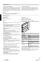
Auxiliary function for DHW heating
In solar thermal systems with DHW storage, we recommend heating
the preheating cylinder and the preheating stage in dual mode DHW
cylinders to ≥ 60 °C once a day (regardless of the cylinder volume).
Enabling of the auxiliary function for DHW heating must be program-
med at the boiler control unit. The solar preheat stage can be heated
up at selectable times.
Relay kick
If the pumps and valves have been switched off for 24 hours, they
are started for approx. 10 s to prevent them seizing up.
Reduction of stagnation time
If there is an excess of solar energy, the speed of the solar circuit
pump is reduced before the maximum cylinder temperature is
reached. This causes an increase in the differential between collec-
tor temperature and cylinder temperature. The heat transfer to the
DHW cylinder is reduced, which delays stagnation.
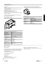
EM-EA1 extension
Part no. Z017412
■ PlusBus subscriber
■ Enclosure for wall mounting
Functions
Note
Only one function can be connected to each EM-EA1 extension (DIO
electronics module).
■
230 V fault message input and fault message output (poten-
tial-free) without system blocking
Fault message input: If a voltage of 230 V is present at digital input
contact 43-1, fault message is active. Fault message output 66
active.
■
External LPG valve
Output 43-L is active if the burner control unit opens the external
LPG valve.
■
Extractor hood: External extractor interlock
An extractor can be switched off. Output 66 switches from Ö to S
and thereby switches the extractor hood off when the burner con-
trol unit starts the burner.
■
Changing operating modes
Demand to all available heating circuits simultaneously, as long as
contact remains closed. With the set room temperature of each
individual heating circuit:
DI1 Reduced room temperature
DI2 Standard room temperature
DI3 Comfort room temperature
■
Fault message input 24 V and system blocking
, e.g. conden-
sate removal pump
If contact DI1 is closed, the heat generator is blocked. Output 66 is
switched over. Fault message F.104 appears. E.g. block burner if
fault is present at condensate removal pump.
Note
If only the fault message output is to be used, set e.g. the "fault
message input... and fault message output" functions.
■
Fault message input 230 V and system blocking
If a voltage of 230 V is present at digital input contact 43-1, the
heat generator is blocked. Output 66 is switched over. Fault mes-
sage F.104 appears.
■
External demand (digital)
If a voltage of 230 V is present at digital input contact 43-1, a
demand is sent to the heat generator with an adjustable set flow
temperature (parameter 528.0) and a set speed for the primary cir-
cuit pump (parameter 1100.2).
■
External blocking
If a voltage of 230 V is present at digital input contact 43-1, the
heat generator is blocked. Message info I.57 is displayed.
Components:
■ DIO electronics module
■ Plug for connecting the functions
■ Power cable (3.0 m long) with plug
■ PlusBus connecting lead (3.0 m long) with plug
64
240
231
Specification
Rated voltage
230 V~
Rated frequency
50 Hz
Rated current
2 A
Power consumption
2.8 W
Rated breaking capacity
output 66 (potential-free)
1 A 230 V~
Output 43 rated breaking
capacity
1 A 230 V~
Protection class
I
IP rating
IP 20D to EN 60529; ensure through
design/installation.
Permissible ambient temperature
– Operation
0 to +40 °C
Installation in living spaces or boiler
rooms (standard ambient conditions)
– Storage and transport
–20 to +60 °C
Demand to digital input DI to DI3
External contacts must be potential-free. When connecting, observe
the requirements of protection class II, i.e. 5.0 mm air and creep
path and 2.0 mm insulation thickness to live parts.
Control unit
(cont.)
150
VIESMANN
VITODENS
9
5853906
Summary of Contents for Vitodens 200-W B2HE
Page 154: ...154 VIESMANN VITODENS...
Page 155: ...VITODENS VIESMANN 155 5853906...


