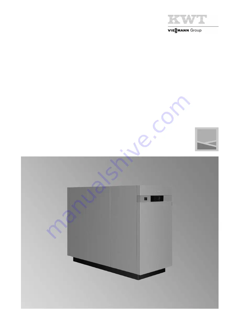
background image

Installation and service instructions

for contractors

Vitocal 300-G Pro
Type  BW 301.B090 to 302.B250
Vitocal 300-W Pro
Type  WW 301.B125 to 302.B300

For applicability, see the last page

VITOCAL 300-G PRO

VITOCAL 300-W PRO

5549 984 GB

9/2014

Please keep safe.

Summary of Contents for KWT BW 301.B090

Page 1: ...tructions for contractors Vitocal 300 G Pro Type BW 301 B090 to 302 B250 Vitocal 300 W Pro Type WW 301 B125 to 302 B300 For applicability see the last page VITOCAL 300 G PRO VITOCAL 300 W PRO 5549 984...

Page 2: ...olate the system from the power supply e g by removing the separate fuse or by means of a mains isolator and check that it is no longer live Note In addition to the control circuit there may be severa...

Page 3: ...stage 2 stage 21 Type WW 301 B125 to WW 302 B300 21 Water water cascade 1 stage 2 stage 22 Primary circuit Water water with separating heat exchanger cas cade type BW 301 B090 to BW 302 B250 22 Elect...

Page 4: ...of internal components type BW 301 B090 to BW 302 B250 68 Overview of internal components type WW 301 B125 to WW 302 B300 69 Draining the heat pump on the primary secondary side 70 Checking sensors 70...

Page 5: ...epair shutdown X X X X X Dismantling removal collection X X X X X Disposal X X X Occupational safety Electrical connections Danger Electromagnetic radiation near the wiring cham ber of the heat pump c...

Page 6: ...or to commissioning and following repair or maintenance work check that the heat pump is in the intended condition Danger Falling of heavy or unwieldy heat pump compo nents can result in life threaten...

Page 7: ...d refrigeration engi neer Wear suitable protective clothing Work on the casing Danger Breaking through the knockouts on the back panel leaves behind sharp edges from the metal retaining tabs that can...

Page 8: ...valve EEV with an independent control circuit refrigerant circuit controller The heat pump control unit can switch and regulate one cooling circuit The cooling circuit may be a heating circuit prepar...

Page 9: ...ight see Specification page 88 Suitable equipment for unloading the lorry must be available on site see the following chapter Please note Prevent equipment damage when unloading and handling the heat...

Page 10: ...e g 2 or 3 layers of corrugated cardboard D Belt strap suitable for the shipping weight Note Lifting with belt straps is only permitted without fitted side panels and front or back panels Handling by...

Page 11: ...80 1190 kg BW 302 B250 1300 kg Total weight type WW 301 B125 to WW 302 B300 WW 301 B125 1015 kg WW 301 B155 1055 kg WW 302 B125 1035 kg WW 302 B155 1060 kg WW 302 B200 1330 kg WW 302 B250 1380 kg WW 3...

Page 12: ...tion set and Victaulic flange adaptor set 2 or 3 version 1000 mm On site hydraulic connections 600 mm E Without anti vibration parts side sections 855 mm Note When installing cascades 2 to 5 heat pump...

Page 13: ...t pump feet Type BW 301 B090 BW 301 B120 BW 302 B090 BW 302 B120 1400 1000 1064 709 F E Fig 6 E Pressure tested sound insulation layer approx 10 mm F Front of the heat pump Type BW 302 B150 BW 302 B18...

Page 14: ...nsions type BW 301 B090 to BW 301 B120 BW 302 B090 and BW 302 B120 Back panel BW 1 SWEP 1343 1650 911 A B D E H 1243 646 496 946 1093 368 367 G F C Fig 9 A Primary circuit brine inlet Victaulic 3 B an...

Page 15: ...400 V 50 Hz Note Observe the separately supplied dimensions for pipe knock outs Combination of knock outs to be used with back panel BW 1 SWEP Type Knockouts applicable First knockout BW 301 B090 A C...

Page 16: ...circuit return Victaulic 2 E Power supply 400 V 50 Hz F Low voltage 50 V G Power supply 230 V 50 Hz Note Observe the separately supplied dimensions for pipe knock outs Type WW 302 B200 WW 302 B250 WW...

Page 17: ...nnections between several heat pumps on site All components required for the cooling circuit must be provided on site This must be achieved with an appropriately sized plate heat exchanger Primary cir...

Page 18: ...e must be produced during partial load Electrical installation scheme For a summary of electrical connections see from page 37 and separate Connection and wiring diagram Primary circuit brine water 2...

Page 19: ...T for partial load wU Geothermal probes Electrical installation scheme For a summary of electrical connections see from page 37 and separate Connection and wiring dia gram Primary circuit brine water...

Page 20: ...wP Brine safety assembly wQ Pressure switch primary circuit wW Brine distributor geothermal probes collectors wT Primary pump heat pump II fail safe Note For 2 stage Vitocal 300 G Pro a primary pump...

Page 21: ...rimary circuit wW Separating heat exchanger primary circuit wE Flow switch well circuit remove jumper when connecting wR Dirt trap wT Optional Primary pump 2 fail safe for stage 2 Observe minimum flow...

Page 22: ...heat exchanger cascade type BW 301 B090 to BW 302 B250 Hydraulic installation scheme wQ 2 1 P 2 LP1 X3 8 3 9 211 1 230V LP1 X3 8 3 9 F2 F3 KM BUS 2 9 211 1 230V LP1 X3 8 3 9 F2 F3 KM BUS qT 2 211 1 w...

Page 23: ...it wW Separating heat exchanger primary circuit wE Flow switch well circuit remove jumper when connecting wR Dirt trap wT Primary pump heat pump II fail safe Note For two stage Vitocal 300 G Pro a pri...

Page 24: ...quired equipment Pos Designation 1 Heat pump 2 Integral heat pump control unit Integral frost stat primary circuit Integral flow switch well circuit wR Dirt trap wZ Well pump suction pump for groundwa...

Page 25: ...tion pump for groundwater fail safe connect to each heat pump via on site contac tor with MCB fuse protection wU Delivery well wI Return well Electrical installation scheme For a summary of electrical...

Page 26: ...rface to heating water buffer cylinder flow P Interface to primary circuit flow Q Interface to primary circuit return W Interface to the DHW cylinder I Lead heat pump in the heat pump cascade single o...

Page 27: ...cheme For a summary of electrical connections see from page 37 and separate Connection and wiring dia gram DHW heating Type BW 301 B090 to BW 302 B250 and WW 301 B125 to WW 302 B300 Hydraulic installa...

Page 28: ...y of electrical connections see from page 37 and separate Connection and wiring dia gram Required parameter settings for DHW heating Set the required parameters during commissioning see from page 57 P...

Page 29: ...g the transport brackets Please note If transport brackets are not removed they cause vibrations and excessive noise Remove and dispose of all 4 transport brackets correctly Installation sequence Siti...

Page 30: ...the heat pump horizontally as described on page 11 1 Fit the back panel see illustration below 2 Connect the appliance hydraulically and electrically see page 34 and page 48 3 Fit the side panels see...

Page 31: ...31 Fitting the outer panels 4 3 5 1 2 6 4 3 Fig 24 Note The numbered arrows indicate an installation step Installation sequence Siting the heat pump cont 5549 984 GB Installation...

Page 32: ...upply 400 V 50 Hz Note Observe the separately supplied dimensions for pipe knock outs Note The illustration above relates to versions with SWEP heat exchangers Overview of connections Type WW 301 B125...

Page 33: ...Heat pump connections Use of the 2 or 3 connection set accessories 800 A B C D Fig 27 A Victaulic couplings 2 secondary circuit or 3 primary circuit B Flexible connection line with anti vibration ele...

Page 34: ...A B C D Fig 29 1 Clean all Victaulic connections 2 Open Victaulic coupling B around 1 cm 3 Push Victaulic coupling B with inserted gasket as far as it will go onto connection pipe A inside the heat p...

Page 35: ...ry lines inside the building with ther mally insulating and vapour diffusion proof materi als 5 Charge the primary circuit with Viessmann heat transfer medium and vent Connecting the secondary circuit...

Page 36: ...s can not drift into the adjacent voltage area When routing on site power cables observe the loca tion of the cable entries into the appliance through the back panel see page 14 to page 16 400 V 230 V...

Page 37: ...116 3 116 116 K1 116 4 116 116 K1 116 5 116 116 K1 116 6 116 16 LP1 X3 16 N LP1 X2 N 3 K1 X3 3 4 K1 X3 4 116 K2 116 1 116 116 K2 116 2 116 116 K2 116 3 116 116 K2 116 4 116 116 K2 116 5 116 116 K2 116...

Page 38: ...als 211 1 224 2 see separate connection and wiring diagram sheet 20 Secondary pump s On site connection see separate connection and wiring diagram sheet 13 Factory wiring on main and expansion PCB ter...

Page 39: ...rent 4 2 A Connection see separate Connection and wiring dia gram sheet 110 211 5 NC Cooling control NC function natural cooling or NC signal for AC function active cooling Connection values Output 10...

Page 40: ...equired see separate Connection and wiring diagram sheet 121 sheet 122 212 3 DHW circulation pump Connection values Output 50 W Voltage 230 V Max switching current 4 2 A Connection see separate Connec...

Page 41: ...te Connection and wiring diagram sheet 170 sheet 171 sheet 172 Plug sXF Terminals Function Explanation 224 4 r 2 Instantaneous heating water heater switching stage 2 Connection values Output 10 W Volt...

Page 42: ...xer motor control heating circuit M2 HC2 Signal mixer CLOSE Connection values Output 10 W Voltage 230 V Max switching current 0 2 0 1 A Connection see separate Connection and wiring dia gram sheet 130...

Page 43: ...1 116 4 116 116 K1 116 5 116 116 K1 116 6 116 16 LP1 X3 16 N LP1 X2 N 3 K1 X3 3 4 K1 X3 4 116 K2 116 1 116 116 K2 116 2 116 116 K2 116 3 116 116 K2 116 4 116 116 K2 116 5 116 116 K2 116 6 116 16 LP1 X...

Page 44: ...ed No power OFF safety chain has continuity Open Power OFF enabled Breaking capacity 230 V 0 15 A There must not be a jumper when the power OFF con tact has been connected Note No parameters need to b...

Page 45: ...ternal H1 extension no other external function can be connected to the external H1 extension K2 220 2 K2 220 3 Only for 2 stage heat pumps Blocking compressor 2 in connec tion with DHW heating Connect...

Page 46: ...0 Programming unit connection X24 Slot for LON communication module X25 Terminals for internal sensors and components Connections for connecting cable LV to the heat pump control panel or wiring chamb...

Page 47: ...0 k NTC F17 Never connect anything here X25 13 14 Return temperature sensor secondary circuit for heat pump stage 2 if in stalled connect on site Pt500A PTC F20 Boiler water temperature sensor externa...

Page 48: ...sed e g instantane ous heating water heater immersion heater in heating water buffer cylinder Connection Appliance installation instructions Electrical connection see separate connection and wiring di...

Page 49: ...dia gram Protect the power supply to the heat pump control unit with an MCB fuse of max 16 A For accessories and external components that are not to be connected to the heat pump control unit connect...

Page 50: ...supply utility so a sepa rate power supply is required for the control circuit A separate connection for the control circuit calls for the internal wiring to be changed This wiring work may only be c...

Page 51: ...the tolerance range of the electronic soft starter is exceeded the soft starter will automatically separate the appliance from the mains Remove the cause if the relay has responded The relay does not...

Page 52: ...4 Phase loss Motor not connected 5 Phase asymmetry 6 Short circuited Thyristor 7 Test Installing the programming unit Note The programming unit is delivered inside the wiring chamber of the heat pump...

Page 53: ...rommets with adhesive tape if nec essary 1 Prior to closing the heat pump check the following Are all cables inside the wiring chamber securely attached strain relief cable ties Has the programming un...

Page 54: ...the secondary side 56 6 Charging and venting the solar circuit 56 7 Checking expansion vessels and the primary circuit heating circuit pressure 57 8 Commissioning the system 57 9 Check electronic flo...

Page 55: ...see page 53 Regarding commissioning this appliance see also the operating instructions Writing reports Enter all readings taken during the commissioning described below into the reports from page 80...

Page 56: ...appliance damage check the flow and return connections of the heat pump sec ondary circuit for tightness In the case of leaks switch off the heat pump immediately drain the secondary circuit and chec...

Page 57: ...result in damage to the appliance and the heat ing system Observe the service instructions for the Vitotronic 200 heat pump control unit other wise the appliance warranty will be void Switch on the O...

Page 58: ...taneously for approx 4 s Disabling the service menu The service menu remains active until it is ended with Terminate service alternatively it ends if no oper ation takes place for 30 min Setting param...

Page 59: ...finition System scheme 7000 With DHW heating DHW circulation pump Extended menu Time program DHW circulation Set time program Mixer extension kit for heating cir cuit M3 HC3 System definition System s...

Page 60: ...ressor mixer in control mode or OPEN System definition Effect of external demand on heat pump heating circuits 7014 0 to 7 Observe parameter Flow temperature for external de mand 730C External changeo...

Page 61: ...nable external heat source for DHW heating 7B0D 1 Swimming pool water heating Parameters for swimming pool heating Setting System definition External extension 7010 1 or 3 System definition Swimming p...

Page 62: ...consumption Enable own energy consumptn for set DHW temperature 2 7E10 1 Enable own energy consumption for DHW heating 7E11 1 Enable own energy consumptn for heating water buffer cyl 7E12 1 Enable own...

Page 63: ...cation module installed Enable LON communication module 7710 1 1 LON system number 7798 1 to 5 1 to 5 LON subscriber number 7777 Each number can only be allocated once 1 to 99 1 to 99 LON fault manage...

Page 64: ...required carry out an operating display adjustment High Flow balancing see below for example if circulation pumps had to be sized for higher flow rates LED 0 flashes green Flow rate below minimum flow...

Page 65: ...at monitors the refrigerant tem perature on entry into the compressor Note The frost stat switching points are factory set Adjusting these switching points is possible in special cases for example if...

Page 66: ...the heat pump if parameter 1PF is set to ON Only switch 1PF to ON for short term emer gency operation for example in the event of a sensor break Closing the heat pump Instructing the system user The...

Page 67: ...at the bottom and remove it around 60 cm working space 3 Put the front panel aside taking into consideration the length of the connecting cable and secure it against falling over 4 Remove the top pane...

Page 68: ...302 B180 BW 302 B250 Hot gas temperature sensor Compressor 2 Stage 2 qP Only type BW 302 B090 BW 302 B120 BW 302 B150 BW 302 B180 BW 302 B250 Compressor 2 Stage 2 qQ Hot gas temperature sensor Compre...

Page 69: ...ressure 2 Stage 2 4 High pressure sensor EEV 5 Suction gas temperature sensor EEV 7 Liquid gas temperature sensor EEV 8 Electronic expansion valve EEV 9 Only type WW 302 B125 WW 302 B155 WW 302 B200 W...

Page 70: ...ition Outside temperature sensor F0 Flow temperature sensor heating circuit M2 HC2 F12 Cooling circuit flow temperature sensor direct heating circuit A1 HC1 or separate cooling circuit SKK F14 Room te...

Page 71: ...y as far as it will go Hydraulic line touches the heat pump casing Hydraulic line not connected free of load and torque stress Anti vibration elements for hydraulic connection missing Dismantling Disp...

Page 72: ...90 x 7841391 x x x x x x x Plate evaporator 7842382 x x 7842383 x x 7842384 x 7842385 x 7842386 x Plate condenser 7842387 x x 7842388 x x 7842389 x 7842390 x 7842391 x Oil compensation line 7842379 x...

Page 73: ...nel 7841397 x x x x x x x Casing cover small 7841398 x x x x Casing cover medium 7841399 x x x Casing cover large 7841400 Rear panel BW 7842372 x x x x x x x Side panel left 7841403 x x x x x x x Side...

Page 74: ...eutral conductor 7838011 x x x x Retainer NH elements 7841330 x x x x x x x NH fuses 7842403 x x 7842404 x x 7842405 x 7842406 x 7842407 x Main contactor 7842408 x x 7842409 x x 7842410 x 7842411 x x...

Page 75: ...x x x Fixings EEV 7838041 x x x x x x x Cable fitting winding protector 7838042 x x x x x x x Mating plug 7832896 x x x x x x x 7832897 x x x x x x x 7832898 x x x x x x x Temperature sensor 7438702 x...

Page 76: ...6 x x x Soldering adaptor 7837957 x x x High pressure sensor 7833089 x x x x x x x Low pressure sensor 7833090 x x x x x x x Filter dryer 7842377 x 7842378 x x 7837961 x x x x EEV 7837964 x x x 783796...

Page 77: ...Fascia medium 7841407 x x x x Fascia large 7841408 x x x Vitotronic programming unit 7842371 x x x x x x x Cable entry 7837992 x x x x x x x 7837995 x x x x x x x Labelling hydraulic connections 7837...

Page 78: ...ary contact for contactors 7841417 x x x x x x x Base for auxiliary relay 7841418 x x x x x x x Relay 7841419 x x x x x x x Circuit protection circulation pump 7838025 x x x x x x x Neutral conductor...

Page 79: ...x x x x 7832897 x x x x x x x 7832898 x x x x x x x Temperature sensor 7438702 x x x x x x x Cable harness EEV sensor 7843356 x x x x x x x Outside temperature sensor 7837053 x x x x x x x EEV extensi...

Page 80: ...T If secondary circuit flow temperature 35 C primary circuit flow temperature 10 C K 3 to 5 If secondary circuit flow temperature 35 C primary circuit flow temperature 0 C K 2 to 4 Testing the mixer...

Page 81: ...ating circuits 7015 4 Vitocom 100 7017 0 Effect of external blocking on pumps compressor 701 A 0 Common flow temperature sensor sys tem 701 B 0 Number of lag heat pumps in cascade 7029 0 Select primar...

Page 82: ...sen sor 7B11 1 DHW Parameter Code Delivered condition Commission ing Maintenance Service Set DHW temperature 6000 500 50 C Min DHW temperature 6005 100 10 C Max DHW temperature 6006 600 60 C Hysteresi...

Page 83: ...heating 7902 1 Max output instantaneous heating wa ter heater 7907 3 Output for instant heating water heater at power OFF 790 A 0 Dual mode temp instant heating water heater 790 B 500 50 C Internal h...

Page 84: ...te control 2003 0 Heating curve level 2006 0 0 K Heating curve slope 2007 6 0 6 Influence room temperature hook up 200 A 10 Room temperature hook up 200 B 0 Max flow temperature heating circuit 200E 4...

Page 85: ...eparate cooling circuit 7106 0 Cooling curve level 7110 0 0 K Cooling curve slope 7111 12 1 2 Remote control cooling circ 7116 0 Enable coolant buffer cylinder 7120 0 Enable active cooling 71FE 0 Vent...

Page 86: ...ption for heating 7E13 0 Raise set DHW cylinder temperature PV 7E21 0 0 K Raise set heating water buffer cylinder temp PV 7E22 0 0 K Raise set room temperature PV 7E23 0 0 K Time Parameter Code Delive...

Page 87: ...outside temperature 77FC 0 Send outside temperature 77FD 0 Source time 77FE 0 Send time 77FF 0 Control Parameter Code Delivered condition Commission ing Maintenance Service Lock out controls 8800 0 C...

Page 88: ...er secondary circuit Content l 22 7 28 7 22 7 28 7 38 7 53 5 57 1 Nominal flow rate to EN 14511 m h 16 0 21 0 15 4 20 3 25 8 31 4 41 4 Minimum flow rate 10 K spread m h 8 0 10 5 7 8 10 2 12 9 15 7 20...

Page 89: ...up or down Operation as water water heat pump with intermedi ate circuit If the brine temperature of the intermediate circuit is reduced to 8 C instead of 10 C the heat pump out put is reduced by appr...

Page 90: ...18 18 18 18 Permiss operating pressure high pressure side bar 43 43 43 43 43 43 43 No of hermetically sealed scroll compressors Type 1 1 2 2 2 2 2 Permiss operating pres sure Primary circuit bar 6 6 6...

Page 91: ...28 7 38 7 53 5 57 1 Nominal flow rate to EN 14511 m h 20 0 24 1 19 3 24 9 32 7 41 3 49 9 Minimum flow rate 10 K spread m h 11 0 12 5 10 0 12 5 16 4 20 7 25 0 Flow pressure drop at mini mum flow rate...

Page 92: ...Permiss operating pressure high pressure side bar 43 43 43 43 43 43 43 No of hermetically sealed scroll compressors Type 1 1 2 2 2 2 2 Permiss operating pres sure Primary circuit bar 6 6 6 6 6 6 6 Se...

Page 93: ...lines fully installed Components for cooling mode fully installed All circulation pumps are connected and programmed for correct speed and the maintaining of the re quired flow rates has been checked...

Page 94: ...guide can be utilised to assess the energy consumption of heating and ventilation systems to DIN V 4701 10 specified by the EnEV Germany Worb 01 09 2014 KWT K lte W rmetechnik AG Viessmann Group We K...

Page 95: ...r the product Vitocal 300 G Pro see technical guide can be utilised to assess the energy consumption of heating and ventilation systems to DIN V 4701 10 specified by the EnEV Germany Worb 01 09 2014 K...

Page 96: ...l information 8 Heat pump control unit 37 71 Routing cables leads 36 Electrical connections 37 Overview 37 Electrical installation scheme Primary circuit brine water 18 19 20 22 25 27 28 Electric boos...

Page 97: ...1 For external extension 60 For heating circuit pump 59 For mixer extension kit 59 For Vitocom 100 60 Heat pump stage 2 60 Instantaneous heating water heater 61 On site components 59 Other components...

Page 98: ...settings 61 Swimming pool 48 Switching point Flow switch 65 Frost stat 65 System pressure checking 56 57 System user instruction 66 T Temperature sensor hot gas 68 69 Temperature sensor suction gas 6...

Page 99: ...99 5549 984 GB...

Page 100: ...2 7542683 7542684 7542685 Viessmann Limited Hortonwood 30 Telford Shropshire TF1 7YP GB Telephone 44 1952 675000 Fax 44 1952 675040 E mail info uk viessmann com Viessmann Werke GmbH Co KG D 35107 Alle...

Reviews: