6
VE106 Groove-N-Go Tool
TOOL SETUP
The standard VE106 Groove-N-Go tool is
intended for field or shop setup. Before groov-
ing, the adjustable legs must be mounted
onto the tool.
1.
Remove all components from the pack-
aging, and make sure all necessary items are
included. Refer to the "Receiving the Tool"
section on page 3.
2.
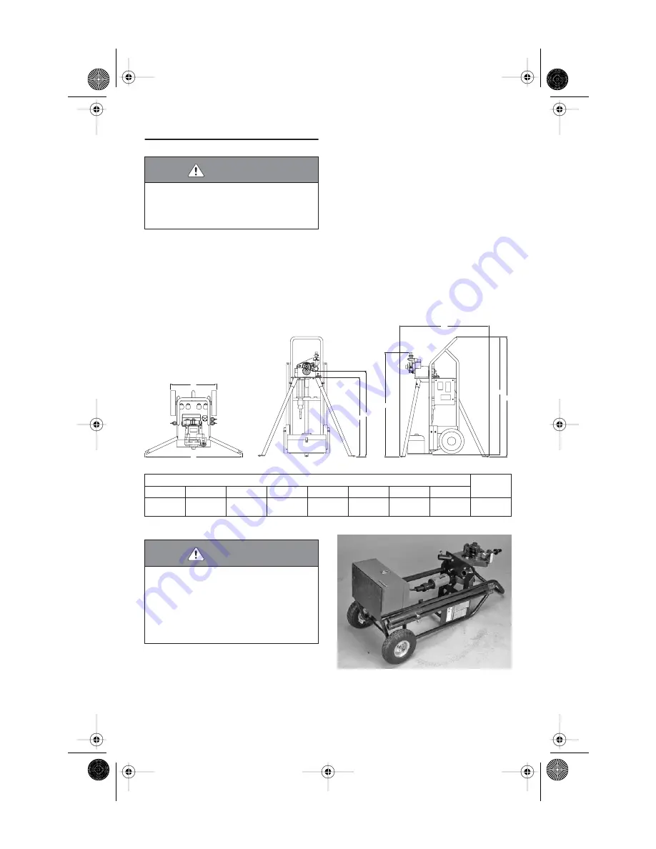
Select a location for the tool by taking
into consideration the following factors (refer
to the drawing below for overall dimensions):
2a.
The required power supply (verify the
voltage of the drive motor [110 volt or
220 volt])
2b.
Adequate space to handle pipe/tubing
lengths
2c.
A firm and level surface for the tool and
pipe stand
2d.
Adequate clearance around the tool
for adjustment and maintenance
3.
Make sure the tool is secure and in the
horizontal position (lying down) with the han-
dle of the cart resting against the ground or
floor, as shown above.
WARNING
• DO NOT connect the tool to the electrical source
until instructed otherwise.
Accidental startup of the tool could result in serious
personal injury.
B
A
C
D
G
F
E
H
Plan View
Front View
Dimensions – inches (millimeters)
Tool Weight
lbs/kg
A
B
C
D
E *
F
G
H
22.00
39.50
32.25
35.00
45.00
40.50
48.75
49.00
162
(558,8)
(1003,3)
(819,2)
(889,0)
(1143,0)
(1028,7)
(1238,3)
(1244,6)
73,5
* “E” dimension reflects maximum ram extension.
WARNING
• DO NOT lift the tool into the vertical (upright) posi-
tion until the two front legs are installed.
• The tool will be top heavy until the third leg is
installed on the tool. Use caution to prevent the tool
from tipping over.
Failure to follow these instructions could result in
serious personal injury.
Side View
TM-VE106 3736 Rev_B.fm Page 6 Monday, May 9, 2005 12:02 PM


