18
VE106 Groove-N-Go Tool
11.
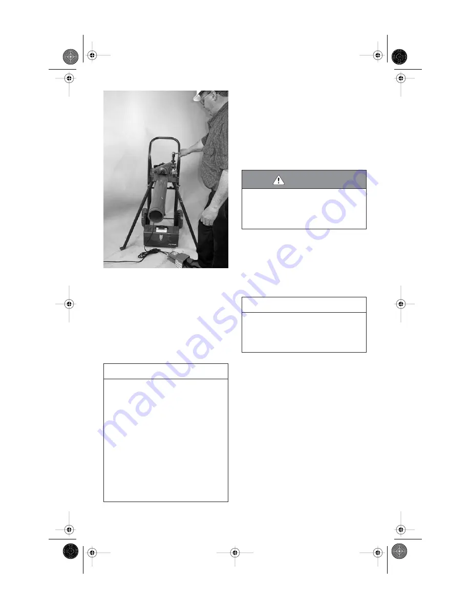
Depress and hold down the safety foot-
switch pedal. The pipe/tubing will begin to
rotate counterclockwise. As the pipe/tubing
rotates, begin the grooving process by rotat-
ing the feed screw
clockwise
slowly with the
3
/
8
-inch square-drive ratchet. Make sure the
pipe/tubing remains against the lower-roll
backstop flange. If the pipe/tubing does not
remain against the lower-roll backstop flange,
release the safety foot switch, and re-position
the pipe/tubing.
12.
Continue the grooving process until the
groove diameter stop makes firm contact with
the top of the body nut.
13.
Continue to rotate the pipe/tubing for one
to three revolutions to ensure groove comple-
tion.
14.
Release the safety foot switch pedal, and
withdraw foot from the safety foot switch.
15.
If a short length of pipe/tubing is in the
tool, manually support the pipe/tubing.
16.
To release the pipe/tubing, retract the
upper roll by turning the feed screw
counter-
clockwise
. Remove the pipe/tubing from the
tool.
NOTICE
• Groove light-wall pipe at a moderate rate by forming
grooves uniformly in 5 to 10 pipe rotations.
• Schedule 40 pipe requires more revolutions to reach
the proper groove diameter.
• A shear pin is used to connect the drive socket to
the feed screw. If excessive force is applied to the
3
/
8
-inch square-drive ratchet, the spring pin will
shear and prevent damaging forces from being
applied to tool components.
• The tool is designed to accommodate normal groov-
ing forces. Therefore, shearing the pin should not
occur normally. However, if a pin shears, determine
the cause by referring to the "Troubleshooting" sec-
tion on page 26. Correct the problem, and replace
the sheared pin with a spare pin supplied with the
tool.
WARNING
• DO NOT place hands inside the pipe/tubing end or in
the area of the grooving rolls while the pipe/tubing
is still rotating.
Failure to follow this instruction could result in seri-
ous personal injury.
NOTICE
• The groove diameter must be within specification
for the diameter and wall thickness of pipe/tubing.
The groove diameter should be checked and
adjusted, as necessary, to ensure grooves remain
within specification.
TM-VE106 3736 Rev_B.fm Page 18 Monday, May 9, 2005 12:02 PM


