21
7.3
Technical data of Honeywell V 4044F three-way valve
Tab. №. 5
Technical parameters of Honeywell V 4044F motorized zone-type three-way valve
The maximum differential pressure for valve closing (the maximum pressure-
difference between the input and the output, with which the valve can work)
mbar
550
Maximum ambient temperature
°C
50
Heating water temperature
°C
5 - 88
Connecting dimensions (heating water input and output)
Js
inside thread 1
“
Connecting voltage
1/N/PE 230 V AC 50 Hz TN-S
Electric cover
IP 40
Environment
according to ČSN 33 2000 - 7 – 701 ed. 2,
the boiler mustn't be installed in 0,1,2 zones
Remark: a 5-core connecting cable is delivered together with the valve
1
2
3
4
5
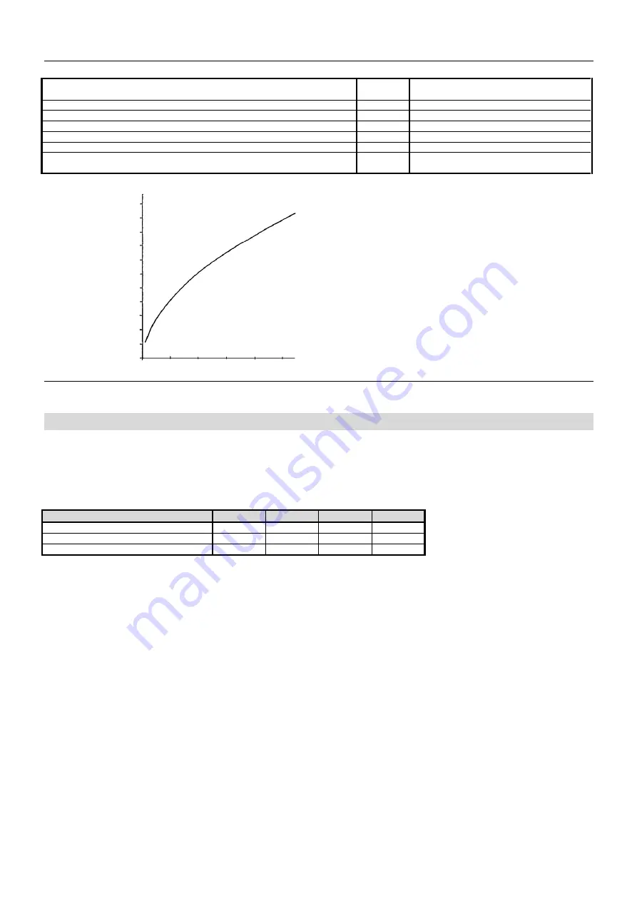
Pressure loss [m of water column]
Fig. №. 18
Honeywell V 4044F three-way valve characteristics
8
Forced flue gases exhaust
The boiler can be equipped with a flue exhauster (only OSV hereinafter) which enables installation of the boiler also in the space where it
cannot be connected to a chimney and flue gases can be led away into the outdoor space through the wall
– according to TPG G 800 01 „Flue
outfall from the gas fuel appliances on the exterior wall (facade)".
This complementary device can be used in the whole output range of boilers designated for natural gas combustion. Two-sectional boilers can
only be operated with rated output.
Tab. №. 6
OSV types assignment to VIADRUS GARDE G 42 ECO boiler
number of sections
2
3
4
5
boiler power (kW)
8
12-17
18-26
22-30
OSV type
OSV 1-2
OSV 1-3
OSV 1-4
OSV 2-5
Neck diameter D (mm)
80
110
130
160
The operation safety is ensured by a differential pressure switch which switches on the burner only on condition of a proper exhaustion. Other
safety element watching the flue gases escape into the boiler room is the flue gases reverse flow safety device which belongs to boilers
standard equipment.
The flue gases venting can be carried out in two ways according to the figures No. 19 and 20:
We recommend using the version according to fig.. 19 provided the boiler is designed so that it complies with observation of the maximum
height of H = 1,5 m and calculations according to table No. 7. The pressure loss is minimum in this design.
Fig. 20 shows an example of a set in a combined design with separate parts; the calculation according to the table No. 7 has to be observed
here, i.e. it means the max. value of flow resistance coefficient must not be exceeded.
The flue-gases exhausting ventilator (OSV) is being put on the boiler draught diverter neck or on the smoke-flue vertical tube inserted in the
neck of the draught diverter. The neck extension must be direct and vertical, its diameter must be the same as the diameter of the neck and it
must not be longer than
H - 1,5 m
.
OSV can rotate round the vertical axis by 90° to the left or to the right depending on the needed direction of flue gases outfall.
Wiring is done through the interconnection with boiler terminal board. Individual conductors are signed by numbers that correspond to numbers
on boiler terminal board:
Terminal no. 8
– blue conductor
Terminal no. 9
– black conductor
Terminal no. 10
– brawn conductor
Terminal PE
– yellow &.green conductor
The jumper between terminals no. 9 and 10 must be removed in the boiler terminal board. Fix the conductor, which is led from the ventilator, in
the point of its entering, to the cladding and the panel with a MEOS clip to protect is against its rapture.
Following principles must be observed when assembling the flue gas ducting:
-
every joint of flue gas ducting must be secured by at least one sheet-metal screw in order to prevent it from disjunction;
-
the length of particular parts insertion is 50 mm;
-
the neck of the ventilator and the draught diverter must be secured by at least two sheet-metal screws in a the opposite position toward
each other at the point of joint;
-
the flue gases exhaust must be led just vertically or horizontally but never downwards (there is only allowed the max. gradie
nt 3°
downwards for condensate outlet; however, due to the high electric power of the ventilator, no condensate should be created);
100
80
60
40
20
Dependence of pressure loss on
flow rate
Flow rate
[l/min]


