
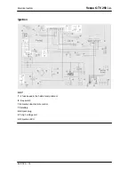

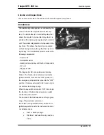

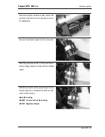
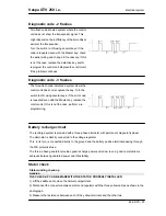


Maximum current output check.
- With engine off and panel set to "ON" turn on the lights and let the battery voltage set to 12V.
- Connect ammeter pliers to the 2 recharge positive poles in output from the regulator.
- Keep the lights on and start the engine, bring it to normal speed and read the values on the ammeter.
With an efficient battery a value must be detected: > 20A
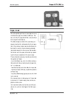
VOLTAGE REGULATOR/RECTIFIER
Specification
Desc./Quantity
Type
Non-adjustable three-phase transistor
Voltage
14 ÷ 15V at 5000 rpm with lights off
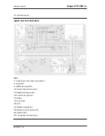
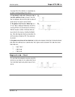
Turn signals system check
Il circuito degli indicatori di direzione viene alimentato dal quadro strumenti. In caso di non funziona-
mento è necessario:
1. verificare efficienza lampade
2. verificare efficienza del fusibile n° 10
3. con commutatore a chiave in ON e senza disconnettere il connettore Gruppo spie , verificare la
presenza di tensione ad intermittenza fra il terminale 8 e massa.
•
In caso di tensione presente verificare la presenza di tensione anche sul commutatore
lampeggiatori. Se questo è alimentato sostituire il commutatore, altrimenti verificare il ca-
blaggio del collegamento commutatore-quadro strumenti.
•
In caso di tensione assente disconnettere il connettore e verificare la presenza di tensione
fra i terminali 4-8 (alimentazione da batteria e massa) e fra i terminali 10-8 (alimentazione
sotto chiave e massa ). Qualora non vi fosse tensione verificare il cablaggio del circuito. In
caso contrario sostituire il quadro strumenti.
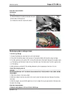
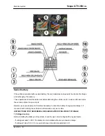
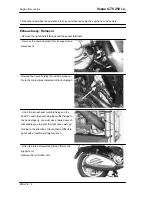
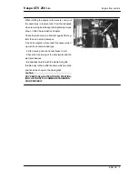
Fuses
The electrical system is equipped with:
1.
six protection fuses «
A
» placed inside the glove
box to the right
2.
two fuses «
B
» located under the helmet com-
partment below the saddle hinge latch.
3.
two fuses «
B
» located under the helmet com-
partment on the left fairing.
The chart shows the position and characteristics
of the fuses in the vehicle.
CAUTION
Vespa GTV 250 i.e.
Electrical system
ELE SYS - 27
Summary of Contents for 633844 IT
Page 4: ......
Page 6: ......
Page 7: ...INDEX OF TOPICS CHARACTERISTICS CHAR ...
Page 21: ...INDEX OF TOPICS TOOLING TOOL ...
Page 34: ...Tooling Vespa GTV 250 i e TOOL 14 ...
Page 35: ...INDEX OF TOPICS MAINTENANCE MAIN ...
Page 48: ...Maintenance Vespa GTV 250 i e MAIN 14 ...
Page 49: ...INDEX OF TOPICS TROUBLESHOOTING TROUBL ...
Page 53: ...INDEX OF TOPICS ELECTRICAL SYSTEM ELE SYS ...
Page 86: ...Electrical system Vespa GTV 250 i e ELE SYS 34 ...
Page 87: ...INDEX OF TOPICS ENGINE FROM VEHICLE ENG VE ...
Page 94: ...Engine from vehicle Vespa GTV 250 i e ENG VE 8 ...
Page 95: ...INDEX OF TOPICS ENGINE ENG ...
Page 152: ...Conceptual diagrams LUBRICATION CIRCUIT Engine Vespa GTV 250 i e ENG 58 ...
Page 153: ...Vespa GTV 250 i e Engine ENG 59 ...
Page 161: ...INDEX OF TOPICS INJECTION INJEC ...
Page 178: ... REMOTE CONTROLS CONTROL UNIT FUSES ETC Injection Vespa GTV 250 i e INJEC 18 ...
Page 182: ...Remove the filter from the pump support Injection Vespa GTV 250 i e INJEC 22 ...
Page 194: ...Injection Vespa GTV 250 i e INJEC 34 ...
Page 203: ...SIGNAL CONTROL Vespa GTV 250 i e Injection INJEC 43 ...
Page 206: ...Injection Vespa GTV 250 i e INJEC 46 ...
Page 207: ...INDEX OF TOPICS SUSPENSIONS SUSP ...
Page 228: ...Suspensions Vespa GTV 250 i e SUSP 22 ...
Page 229: ...INDEX OF TOPICS BRAKING SYSTEM BRAK SYS ...
Page 245: ...INDEX OF TOPICS COOLING SYSTEM COOL SYS ...
Page 248: ...Cooling system Vespa GTV 250 i e COOL SYS 4 ...
Page 249: ...INDEX OF TOPICS CHASSIS CHAS ...
Page 262: ...Chassis Vespa GTV 250 i e CHAS 14 ...
Page 263: ...INDEX OF TOPICS PRE DELIVERY PRE DE ...
Page 267: ...INDEX OF TOPICS TIME TIME ...


