Vertiv™ NetSure™ A50B50 DC Power Retrofit Installation and User Instructions
``
13
Making CAN Interface Board Connections
The CAN Interface Board allows for connecting the A50IFRM and A50EFRM frames together, or to terminate the last frame. This
procedure has been previously described.
This board is also used for other customer inputs/outputs, such as Battery Shunt Input, Load Shunt Input, LVD controls and Battery
Voltage Input via its TB1 connector.
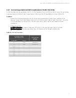
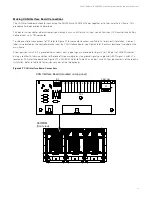
To setup controller connections to TB1, refer to Figure 3.7 for connector locations and Table 3.4 for pin-out information. A pin-out
label is also located on the controller bracket near the CAN Interface board. See Figure 3.8 for the actual location of the label on the
main frame.
A four-position switch (S1) is provided which selects what type of signal is provided to J8 pin 12 (or TB2 pin 1) of A50B50 cabinet
during a rectifier fail alarm condition - either one of three available resistive ground signals, or a ground (+BAT) signal. Switch S1 is
located on CAN Interface board (see Figure 3.7) in A50IFRM. Refer to Table 3.5, and adjust switch S1 per requirements of the specific
installation. Refer to Table 3.6 for resistance values of the three groups.
Figure 3.7
CAN Interface Board Connections
CAN Interface Board (
mounted on top panel
)
J1
J4
TB1
J3
S1
CAN Out
1
2
3
4
5
6
7
8
9
10
11
12
1 2 3 4
OPEN
A50IFRM
(front view)


