Vertiv™ NetSure™ A50B50 DC Power Retrofit Installation and User Instructions
``
7
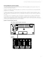
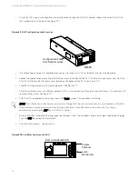
Figure 3.5
IB2 Board Connection
J1
SW1
J11
J12
Relay Output Term. Blocks *
Digital Input Term. Blocks **
Temp Probe #2
Temp Probe #1
J9
J8
J7
J6
J5
J4
J3
J2
Factory-
connected
to Controller
Switch sections must be set to this position
to interface with the controller.
Relay No.
Relay No.
1
8 7 6 5 4 3 2
1
8 7 6 5 4 3 2
Input
No. (
–
)
Input
No. (+)
NO C NC
NO C NC
NO C NC
NO C NC
NO C NC
NO C NC
NO C NC
NO C NC
5 3 1
4
6
2
5
3 1
4
6
2
5 3
1
4
6
2
5 3 1
4
6
2
5 3 1
4
6
2
5 3 1
4
6
2
5 3 1
4
6
2
8
6
4
2
7
5
3
1
**
CAUTION:
DO NOT disconnect any factory wiring when making connections.
Alarm Relays 1 through 5 are available for customer use. Alarm Relays 6 through 8 are used internally.
The relay assigned by the Controller to be the “Critical Summary” alarm or “Major Summary” alarm
(relay 1 by default) will operate in the “Fail Safe Mode”. Fail Safe Mode means the relay is de-energized during an alarm
condition, opening the contacts between the C and NO terminals, and closing the contacts between the C and NC terminals.
The remaining seven (7) alarm relays energize during an alarm condition, closing the contacts between the C and NO
terminals, and opening the contacts between the C and NC terminals.
WARNING:
Observe proper polarity when making Digital Input connections.
Digital Inputs 1-6 can be programmed by the user.
Digital Input 7 is predefined as the external Fuse Alarm input. Customer supplied -48V at J5-1 activates the alarm.
Digital Input 8 is predefined as the ESTOP (Emergency Stop) input. Customer supplied RTN (+48V) at J5-4 activates ESTOP.
*
IB2 Customer
Interface Board
To access connections,
loosen this captive faster
and pull board
part way
out.


