


Vertiv™ NetSure™ A50B50 DC Power Retrofit Installation and User Instructions
4
3.
For CAN connections with only one A50IFRM and one A50EFRM, insert the termination plug into the right-hand CAN port of
the A50EFRM.
Alternatively, if the system is equipped with one or more SMTEMP modules, the fist SMTEMP module's CAN interface should
be connected to the right-hand CAN port of the last A50EFRM. The last SMTEMP module will provide the means to
terminate the CAN per the SMTEMP user instructions, UM547490.
Multiple Shelves
1.
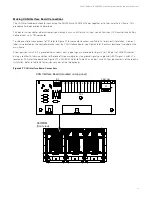
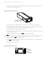
To connect frames installed in different shelves, use the 24-in long CAN cable (P/N 547520) to provide a longer wiring
distance. Refer to Figure 3.4 for a typical configuration of (1) A50IFRM and (8) A50EFRMs.
Figure 3.4 shows one way to make CAN bus connections between retrofit frames in systems with multiple shelves.
You can use the supplied cables in any way that best fits your application. The only requirements are that all retrofit frames
in the system must be connected in series (in any order) and the termination plug must be installed in the last available port.
Alternatively, if the system is equipped with one or more SMTEMP modules, the fist SMTEMP module's CAN interface should
be connected to the right-hand CAN port of the last A50EFRM. The last SMTEMP module will provide the means to
terminate the CAN per the SMTEMP user instructions, UM547490.
2.
Similar to single shelf configuration of terminating the connection, use P/N 547678 CAN terminator/jumper and plug into the
upper right CAT-5 socket of the last frame used.
3.
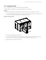
When all CAN connections are made, the front covers can be mounted back on all frames.


