Vertiv™ NetSure™ A50B50 DC Power Retrofit Installation and User Instructions
22
4.3
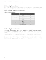
Checking System Status
Observe the status of the indicators located on the Rectifier Modules and Controller. If the system is operating normally, the status of
these is as shown in Table 4.1.
Refer to the NCU Instructions (UM1M830BNA) for additional information.
Table 4.1
Status and Alarm Indicators
Component
Indicator
Normal State
Rectifier
Modules
Power
(Green)
On
Protection
(Yellow)
Off
Alarm
(Red)
Off
NCU
Status
(Green)
On
Observation
(Yellow)
Off
Major or Minor Alarm (Red)
Off
4.4
Checking System Operation
The NCU has been pre-programmed with the required set points and configuration for this application. No adjustments are required.
Refer to the NCU User Manual (UM1M830BNA) for operation of the controller and navigation instructions of the controller menu and
web pages.
Check rectifier alarm. Pull one of the NetSure rectifiers from its frame and verify that the original system level alarm panel registers a
Rectifier Alarm. Re-install the rectifier.
If no alarms are present, contact the Network Operation Center (NOC) that the work has been completed and the alarm log for this
site can be closed. If alarms are present, contact the Vertiv Technical Support desk. Contact information is located near the end of this
document under NetPerform Optimization Services, Technical Support.
.


