


Interfaces and Connectors
EBX-41 Reference Manual
55
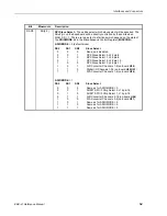
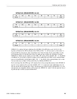
SPISTATUS (READ/WRITE) CA9h
D7
D6
D5
D4
D3
D2
D1
D0
IRQSEL1
IRQSEL0
SPICLK1
SPICLK0
HW_IRQ_EN LSBIT_1ST
HW_INT
BUSY
Table 26: SPI Control Register 2 Bit assignments
Bit
Mnemonic
Description
D7-D6
IRQSEL(1:0)
IRQ Select
– These bits select which IRQ will be asserted when a hardware
interrupt from a connected SPI device occurs. The HW_IRQ_EN bit must be
set to enable SPI IRQ functionality.
IRQSEL1 IRQSEL0
IRQ
0
0
IRQ3
0
1
IRQ4
1
0
IRQ5
1
1
IRQ10
D5-D4
SPICLK(1:0)
SPI SCLK Frequency
–
These bits set the SPI clock frequency.
SPICLK1 SPICLK0
Frequency
0
0
1.042 MHz
0
1
2.083 MHz
1
0
4.167 MHz
1
1
8.333 MHz
D3
HW_IRQ_EN
Hardware IRQ Enable
– Enables or disables the use of the selected IRQ
(IRQSEL) by an SPI device.
0 = SPI IRQ disabled, default
1 = SPI IRQ enabled
Note:
The selected IRQ is shared with PC/104 ISA bus devices. CMOS
settings must be configured for the desired ISA IRQ.
D2
LSBIT_1ST
SPI Shift Direction
– Controls the SPI shift direction of the SPIDATA
registers. The direction can be shifted toward the least significant bit or the
most significant bit.
0 = SPIDATA data is left-shifted (MSbit first), default
1 = SPIDATA data is right-shifted (LSbit first)
D1
HW_INT
SPI Device Interrupt State
–
This bit is a status flag that indicates when the
hardware SPX signal SINT# is asserted.
0 = Hardware interrupt on SINT# is deasserted
1 = Interrupt is present on SINT#
This bit is read-only and is
cleared when the SPI device’s interrupt is cleared.
D0
BUSY
SPI Busy Flag
– This bit is a status flag that indicates when an SPI
transaction is underway.
0 = SPI bus idle
1 = SCLK is clocking data in and out of the SPIDATA registers
This bit is read-only.


