


English
7
6
08.2017
50229 01
50229 01
08.2017
It must be prohibited that foreign particles and liquids
can fall into the fan of motors with vertical shaft orienta-
tion. This shall be done as follows:
Shaft end directed downwards:
The protection cover of the fan is equipped with a
protective roof (supplied condition). Alternatively, the
operator can implement the protection against ingress
of foreign bodies and liquids.
Shaft end directed upwards:
For type of constructions with shaft end upwards the
operator has to ensure that no foreign substances can
fall inside from above. For shaft ends directed upwards
it must be prohibited that water or other liquids can
penetrate into the motor next to the shaft.
During installation of surface cooled motors it has to be
observed that the condensate drain holes are located at
the lowest possible place. If the condensate drain holes
are closed, the screws must be reinserted with a sealant
after drainage of condensation water. If the condensate
drain holes are open, the direct contact with a jet or
gush of water must be avoided. A careful installation
of the motors on an exactly level support has to be
ensured to avoid strain when tightening the machine.
Machines that shall be coupled must be adjusted exact-
ly. If possible elastic couplings shall be used.
Motor connection
The connection has to be done by qualified per-
sonnel according to the valid security regulations.
Outside of Germany the required national standards
must be applied. Name plate designations have to
be observed under all circumstances!
Compare current type, mains voltage and
frequency!
Mind connection type!
Mind rated current for motor protection
switch setting!
For motors with type of protection increased
safety „e“ (“eb”) the t
E
-time and the relative
starting current I
A
/I
N
has to be observed!
Connect the motor according to the connec-
tion diagram inside of the terminal box!
Earthing shall be done with the earthing clip that can be
found at the enclosure or at the end shield depending
on the type of construction. In addition all motors are
equipped with a ground conductor clamp inside of
the terminal box. Unused cable glands of the terminal
box have to be closed for protection against dust and
humidity. For electrical connection the standard security
and starting instructions are valid. The cable glands
or screwed sealing plugs must be admitted for use in
Exapplications. The installation torques, sealing areas
and clamp ranges of the cable clamps given by the
manufacturer have to be observed unconditionally.
Supply cables have to be selected according to
DIN VDE 0100 taking into account rated current and
operational conditions (i.e. ambient temperature, me-
thod of cable installation etc. complying with
DIN VDE 0298 and IEC/EN 60204-1).
For room temperatures of more than 40°C
cables have to be used, that are allowed for
an operation of at least 90°C. This is also
valid for motors that are marked with X on
the supplemental sheet of the EC-type
examination certificate which indicates
special requirements for the cable design.
Take extra care when connecting the supply cables in
the terminal box of the motor. The nuts of the connec-
tion screws have to be fastened without force.
For motors with a terminal board fitted with slotted bolts
according to directive 2014/34/EU (RL94/9/EC) only
cable lugs complying with DIN 46295 shall be used. The
cable lugs are fixed with pressure nuts with integrated
spring washer. Alternatively a solid round wire can be
used. The diameter of the wire must be suitable for
the slot width of the slotted bolt. When inserting the
feed line in the terminal box it has to be secured that
no tensile loading acts on the cables. The inside of the
terminal box must be kept clean. The seals must be un-
damaged and have to be fitting. The terminal box must
always be closed when the motor is in operation.
Attention, do not open terminal boxes in
atmospheres with risk of dust explosions
when they are still hot from operation!
On order type AK 16/5 can be delivered as additional
separate terminal box for motors (IE.-)KPR/KPER 56 -
132S..T. The installer must have the permission to ins-
tall electric equipment in areas with risks of explosions
and must implement the motor connection diagrams.
The creepage distances and air gaps are kept by
preassembly of the terminal board (connection plate)
and the block for connecting PTC thermistors or anti
condensation heating. The type of protection IP 55(66)
is kept by using a closed base plate with 4 x M4 threads
and dimensions 56 x 56, as well as the included seals
and standard parts.
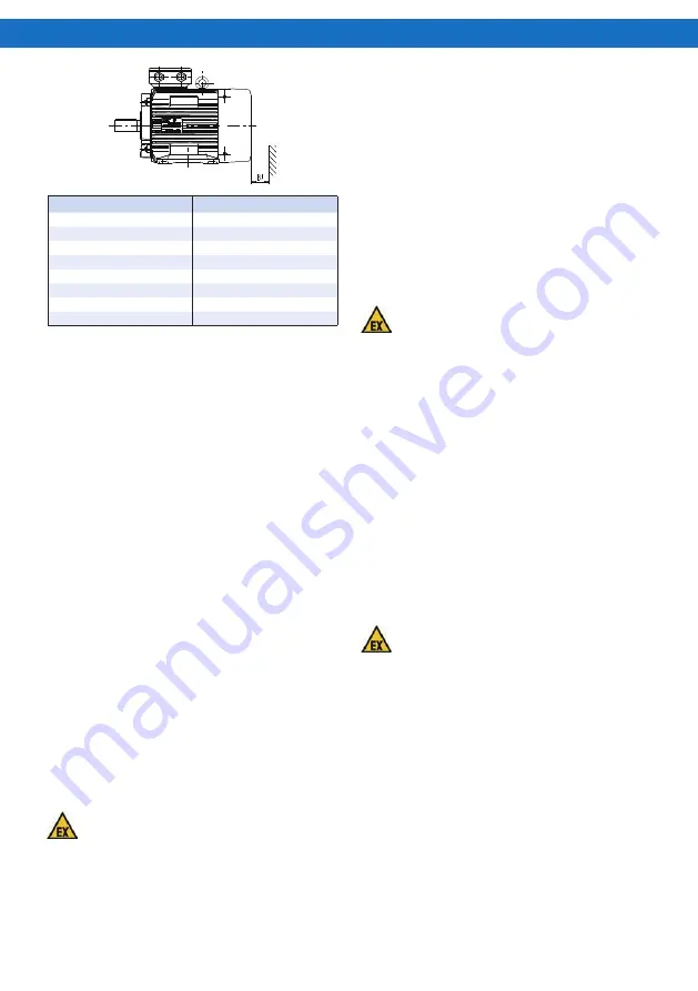
Size
Bl [mm]
63, 71
14
80, 90
16
100, 112
20
132, 160, 180, 200
40
225, 250
90
280 … 315
100
355
110
400
110


