background image

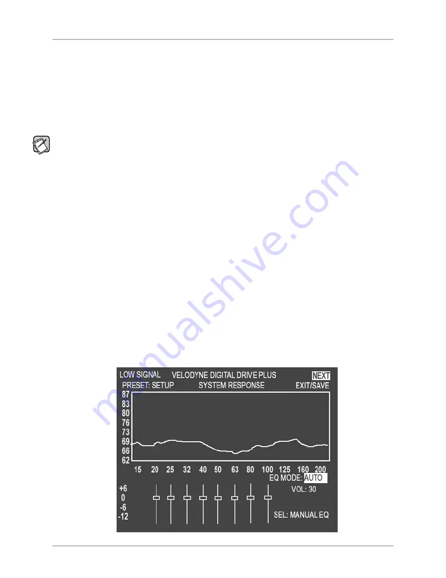
SYSTEM RESPONSE SCREEN

From the 

Introductory

screen you can get to the 

System Response

screen which is used to display the frequency response graph for the

subwoofer’s output. See Figure 3. See the Remote Control Button Sequence Commands table on page 25 for the button sequence.

The 

System Response

screen has the following information and features on it:

• A system response graph that shows the subwoofer’s low frequency output from 15 to 200 Hz. 

• A moving screen pixel marks on the frequency response curve the current frequency of the sweep tone that is playing. 

• 8 parametric filters each of which can be used at its current frequency or adjusted to a frequency and Q you desire between 15

and 200 Hz when in Manual-EQ mode. 

The filter level range is -13db to +6dB although the screen is only marked from -12dB to +6dB.

Status Messages

Status messages appear in the upper left hand corner of the TV screen. In Figure 3, the status message is 

LOW SIGNAL

. The following

status messages appear in this position on the TV screen:

MIC?:

The subwoofer is receiving no signal from the microphone. Microphone is not connected, or either the microphone

or the cable is damaged.

SYNCING:

The subwoofer is trying to synchronize its frequency measurement with the frequency of the sweep tone being

played through your audio system. 

SYNCED:

The subwoofer has synchronized its frequency measurement with the frequency of the sweep tone being played

through your audio system.

LOW SIGNAL:

The receiver output level is too low to perform optimization. Turn up the receiver volume.  After 6 sweeps with

this condition, the subwoofer will reboot.

HIGH SIGNAL:

The receiver output level is too high to perform optimization. Turn down the receiver volume.

VOL..:

Auto-EQ

PLUS

is adjusting subwoofer volume.

CRS..:

Auto-EQ

PLUS

is adjusting subwoofer crossover frequency.

SLP..:

Auto-EQ

PLUS

is adjusting subwoofer crossover filter slope.

PHS..:

Auto-EQ

PLUS

is adjusting subwoofer phase. Auto-EQ

PLUS

doesn’t adjust the polarity of the signal, but rather goes

right to adjusting the phase.

Screen Navigation

You can go to the 

System Settings

screen using the 

NEXT

option in the upper right hand corner of the screen. 

Figure 3: System Response Screen

[ 23 ]

Digital Drive

PLUS

User Interface Manual

TV SCREEN USER INTERFACE FOR OPTIMIZATION

Summary of Contents for DD-10+

Page 1: ...SET UP U S E R I N T E R F A C E M A N U A L Digital DrivePLUS DD 10 DD 12 DD 15 and DD 18...

Page 2: ...t to Your Liking Troubleshooting Guide Uninstalling Velodyne s Digital DrivePLUS Windows Uninstalling the Virtual Com Port Software PA R T T W O T V S C R E E N U S E R I N T E R FA C E F O R O P T I...

Page 3: ...Save and open Digital DrivePLUS files with subwoofer s settings and for Manual EQ only the frequency response curve that results from these settings Save settings to the subwoofer s memory TV Screen D...

Page 4: ...Since the DD subwoofer is a USB device there is more to connecting the subwoofer to your PC than simply installing the USB cable You should always connect the subwoofer to the PC right after running t...

Page 5: ...PLUS Windows Setup Program The Velodyne Digital DrivePLUS Windows Setup Program CD is designed to perform the installation of both the USB Virtual COM driver and the Digital DrivePLUS Windows Setup P...

Page 6: ...ram from your media If the install program doesn t start automatically you can start the installation by double clicking on the VelodyneDD Setup_v exe file in the CD directory in Windows Explorer as s...

Page 7: ...eted message appears and you are prompted to Press any key to continue The installation of the Digital DrivePLUS Windows Setup Program Setup Wizard does not start until you press a key If after a few...

Page 8: ...e dialog window opens Select an install language and then click OK 9 The Velodyne Digital DrivePLUS Setup Program Wizard opens Click Next to continue 6 Digital DrivePLUS User Interface Manual WINDOWS...

Page 9: ...ccept the EULA to continue with the software installation 11 Click Next 12 Browse to where you want to install the Digital DrivePLUS Windows Setup Program The default location is your Windows Program...

Page 10: ...rivePLUS Setup 15 Click Next 16 If you don t want the installation to create a desktop icon for the Digital DrivePLUS Windows Setup Program un check the Create a desktop icon option By default a deskt...

Page 11: ...If you want to run the Digital DrivePLUS Windows Setup Program now select the Launch Velodyne Digital DrivePLUS Setup option 20 Click Finish 9 Digital DrivePLUS User Interface Manual WINDOWS INTERFAC...

Page 12: ...ears as an additional COM port with the label USB Serial Port DIGITAL DRIVEPLUS WINDOWS SETUP PROGRAM USER INTERFACE This section describes the controls and features available in the two user interfac...

Page 13: ...t the maximum or minimum level Moving one of the diamonds at the end of this line towards the filter center diamond raises the filter Q narrowing the bandwidth Moving it away from the filter center di...

Page 14: ...the subwoofer to see the low end frequency response of the satellites of the audio system to which the Digital DrivePLUS subwoofer is matched to Status Information Filename Connection title bar Shows...

Page 15: ...n also allows you to set the Night mode percentage and the auto on setting Figure 2 The Preset Screen Screen Navigation Previous Allows you to return to the Frequency Response and Parameters screen Es...

Page 16: ...r right hand corner Some values are changed with pull down menus like the slopes whereas others increment with up down buttons The parameter input fields can also be selected with the mouse and the va...

Page 17: ...also adjusts the volume crossover slope and phase while these input fields are grayed out during the Auto EQPLUS optimization process 8 You can also watch the status of the subwoofer in the process do...

Page 18: ...at the end of the Auto EQPLUS optimization process All the settings shown in the Windows interface are reverted to those arrived at by the Auto EQPLUS optimization 9 Click Save to DD Now the Digital D...

Page 19: ...caused by the laptop power supply The power supply doesn t have a ground loop isolator which means you can get cross talk noise hum when any USB device including the Digital DrivePLUS subwoofer is co...

Page 20: ...c Click Uninstall a program under Programs 18 Digital DrivePLUS User Interface Manual WINDOWS INTERFACE FOR OPTIMIZATION...

Page 21: ...to the Digital DrivePLUS subwoofer parameters You can leave it on even if you decide to uninstall the Digital DrivePLUS Windows Setup Program as it will give your computer the ability to work with mo...

Page 22: ...ick Uninstall 7 To finish uninstalling the USB Virtual COM Port driver on Windows XP you must remove the driver INF and PNF files manually a In the control panel go to Folder Options View and select t...

Page 23: ...ideo Output yellow RCA connector to the TV s composite video input yellow connector OR The subwoofer s S VIDEO output to the TV s S Video input 2 Use the TV s remote to set the video input where you c...

Page 24: ...n as shown in Figure 2 Figure 2 Introductory Screen with Night Mode and Subwoofer Mute The Introductory screen also shows the current power status if 12V Trigger has been activated if it has gone into...

Page 25: ...is receiving no signal from the microphone Microphone is not connected or either the microphone or the cable is damaged SYNCING The subwoofer is trying to synchronize its frequency measurement with t...

Page 26: ...he buttons on the Velodyne supplied remote control and see the results on your TV screen These controls are described later Tips for Using the TV Screen Controls When using the on TV screen controls R...

Page 27: ...optimization process Restore defaults 8 9 0 Restore defaults and reset the subwoofer Restore last saved volume RESET If volume is changed restores last saved volume Display serial number SELECT Shows...

Page 28: ...Settings Screen To get to the System Settings screen 1 On the System Response screen navigate the cursor to the NEXT field 2 Press SELECT on remote 3 The System Settings screen appears as shown in Fi...

Page 29: ...he screen as shown in Figure 8 Figure 8 System Settings Screen Lock Setup Preset Restore Defaults To restore the factory defaults for all the EQ settings On the Introductory screen press 8 9 0 on the...

Page 30: ...previous settings saved in memory are used Selecting CANCEL and then pressing SELECT on the remote button keeps you on the current screen 4 While the subwoofer is saving its settings you will see the...

Page 31: ...11 3 Press TEST to review the curve with these settings active Be sure to have the mic connected and the Sweep Tone CD playing first Figure 11 System Settings Screen Change Preset Low Pass Crossover...

Page 32: ...ursor over the EQ slider box 3 Press SELECT The values for that particular EQ appear on the right hand side of the screen as shown in Figure 13 Note If all you want to change is the level of each EQ t...

Page 33: ...the accessory kit Carefully snap the microphone into the stand and attach the larger end of the cable to it See the Digital DrivePLUS User s Manual for more information 2 Place the microphone at the...

Page 34: ...rivePLUS Sweep Tone CD into your disc player and press play 5 Once the sweep tone starts to play adjust the receiver or processor output level to about the level of a normal loudness conversation at t...

Page 35: ...System Response screen select the MANUAL option in the EQ MODE area 5 Watch the status messages for SYNCING 6 When the status message says SYNCED start adjusting the subwoofer parameters Do not attem...

Page 36: ...tion to the satellites Raise the level for the subwoofer in the speaker level setup of your surround receiver or processor OR Raise the volume of your Digital DrivePLUS subwoofer after you have finish...

Page 37: ...Power Off Mode Active Waiting for 12 Volt Trigger Mode Figure 19 shows the message displayed when the unit is waiting for a 12 Volt trigger to activate after the AUTO ON OFF MODE is set to 12V TRIGGER...

Page 38: ...ncies or you simply would rather not use the subwoofer s crossover filter To defeat the low pass crossover 1 Navigate to the System Settings screen 2 Move the cursor down to LOW PASS XOVER FREQ and pu...

Page 39: ...dating be sure to read ALL readme txt files and other instruction at the Velodyne website to make sure that you update the software correctly The Digital DrivePLUS subwoofer firmware is updated throug...

Page 40: ...5 2800 voice 408 779 9227 fax 408 465 2851 service voice 408 779 9208 service fax www velodyne com Service E mail service velodyne com General E mail help velodyne com Other trademarks or registered t...

Reviews: