IG-322-EN version 03; 22/07/2022
25
General instructions
SF
6
-insulated circuit-breaker panel:
Type
gae
.630 -1LSV(G)-/5/
in modular extensible design up to 24 kV, 20 kA
Technical description
4.2. Extension of the circuit- breaker panel
The circuit-breaker panel
gae
.630 -1LSV can be extended
using
gae
family panels and block modules. Extensions
are usually added to the right. The design of the complete
switchgear is oriented to the customer’s requirements.
The busbars of the complete switchgear are phase separated
and arranged vertically above each other in the gas tank.
The busbars of the panels to be attached are connected
by means of contact bolts, which are inserted with double
seals into the lateral bushings.
The panels to be attached are laterally connected at two
panel screw connection points.
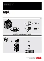
During the installation of the circuit- breaker panel as an
end panel, the side bushings must be secured with sealing
ends to maintain the dielectric strength of the switchgear
(Figure 4.2). The screw plug is to be fitted in the bottom
panel screw connection point.
gae
.630 -1LSV end panels can be delivered with pre-
assembled sealing ends on the lateral bushings.
To attach
gae
.630 panels and block modules and to
assemble end panels, follow the assembly instructions
“Panel screw connection for extensible
gae
.630
panels”, Document
MO-153
.
37250313
1
2
3
4
1
Panel 1
2
Panel 2
3
Top guide pin
4
Bottom guide pin
Figure 4.1.
37250314
Figure 4.2.
Summary of Contents for ORMAZABAL gae.630
Page 63: ......


