AC70T Crane Purpose VFD Manual
71
Appendix: Modbus Communication Protocol
●
Communication Frame Structure
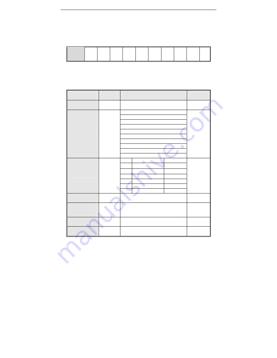
Communication data format is as follows:
The byte composition: Including initiation bit, 8 data bit, check bit and stop bit.
Initiation
Bit
Bit1 Bit2 Bit3 Bit4 Bit5 Bit6 Bit7 Bit8
Chec
k bit
Sto
p bit
One frame message must be transmitted as a continued data flow, and if there is a interval over 1.5 byte before
ending, the receiving equipment will clear the half-baked information. And the next byte will be considered as the
address field of a new frame. Similarly, if the interval between a new frame start-up and the former frame is smaller
than 3.5 byte time, the receiving equipment will consider that it is the continuation of former one frame. Since the
jumbled frame, the final CRC checking value is incorrect, which would lead to the communication mistake.
●
Communication Control Parameter Group Address Specification:
Function
Specification
Address
Definition
Data Meaning Specification
R/W
Characteristic
Communication
Given Frequency
0x3000 or
0x2000
0
~
32000 is corresponding to
0.00Hz
~
320.00Hz
W/R
Communication
Command Setting
0x3001 or
0x2001
0000H: No order
W/R
0001H: FWD running
0002H: REV running
0003H: FWD jog
0004H: REV jog
0005H: DEC stop
0006H: free stop
0007H: malfunction reset
0008H: Running banned command
0009H: Running allowed command
State of Inverter
0x3002 or
0x2002
Bit0 0:
stop
1:running
R
Bit1 0:non-acc
state
1:
ACC
Bit2 0:non-dec
state
1:
DEC
Bit3
0: Forward
1: REV
Bit4 0:
normal
1:
fault
Bit5 0:
GPRS
unlocked 1:GPRS
Bit6
0: no pre- alarm
1: pre alarm
Frequency Inverter
Fault Code
0x3003 or
0x2003
current inverter fault code
(
refer to fault code
table
)
R
Communication
Given Upper
Frequency
0x3004 or
0x2004
0
~
32000
is corresponding to 0.00Hz
~
320.00Hz
W/R
Communication
Torque Setting
0x3005 or
0x2005
0
~
1000 is corresponding to 0.0
~
100.0% W/R
The FWD Max
Frequency limit in
0x3006 or
0x2006
0
~
1000 is corresponding to 0.0
~
100.0% W/R


