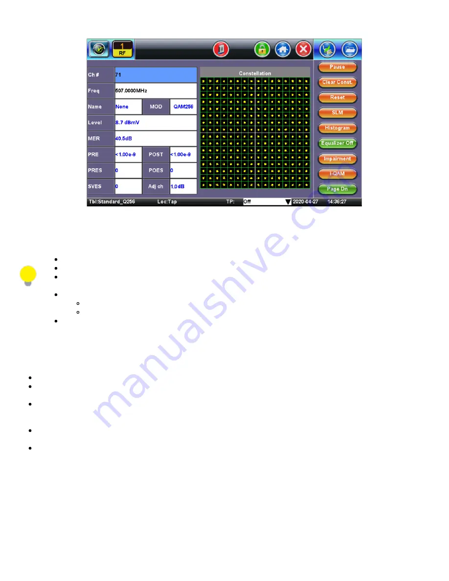
Constellation Diagram - Digital Carriers
Bit Error Rate (BER)
Bit Error Rate (BER) measures how often an error occurs in a given amount of data.
The more errors, the more difficult it is for the FEC circuitry to correct those errors before picture problems occur.
BER is useful for measuring long term system performance and periodic transient impairments that can occasionally
affect system performance.
BER is usually displayed in scientific notation e.g.;
where 1E-3 means one error in every 1000 bits
where 1E-6 is one error in every 1,000,000 bits
Ideally, the signal should have the highest exponent value - the higher the number, the lower the errors.
Constellation diagrams
Constellation diagrams are used to graphically represent the quality and distortion of a digital signal.
The diagram is an X/Y plot of the I (In-phase) and Q (Quadrature) axis components of the QAM signal and is particularly
useful for viewing impairments due to ingress and/or modulation problems present on the digital signal.
A symbol (essentially a waveform representing one or more bits) should ideally appear as a compact or clean dot in the
center of each symbol box. Decision boundaries exist within the constellation so that if the symbol falls within the boundary,
the correct data is received.
If due to noise or other interference, the symbol falls outside the boundary, the data is in error. Error detection and correction
(e.g. FEC) will attempt to the correct these errors, thus avoiding video impairments.
Observing the symbol's shape and location relative to their ideal positions allows some conclusions about the nature of an
impairment
CX380C User Manual RevA00
Page 27 of 105


