


TLC3-BCR-U Thermostat
O
PERATION
Doc: 70-00-0294, V3.1, Date: 20140508
© Vector Controls GmbH, Switzerland
Page 5
Subject to alteration
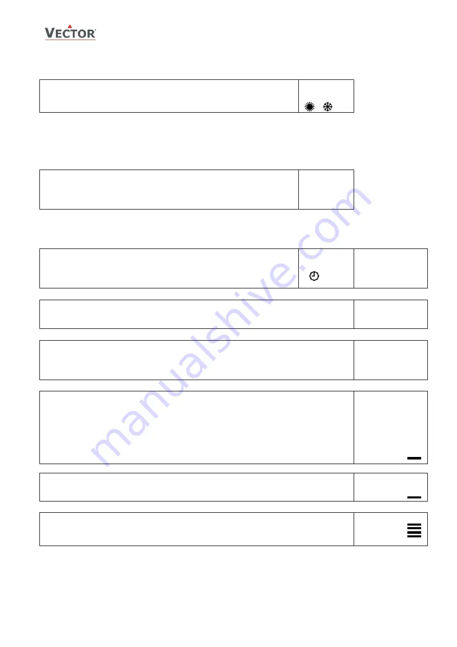
Manual heat – cool change
To manually change heating or cooling mode press the OPTION key for more than 2 seconds.
Access to manual heat – cool change may be disabled with parameter UP03.
For TLC3-BCR-U: Press OPTION > 2 sec. SEL and H-C is displayed.
For TLC3-BCR-U-D: Press OPTION > 2 sec. SEL and current time is displayed.
Press UP key twice. SEL and H-C is displayed.
Press OPTION again to toggle H or C.
SEL
H-C
Clock operation
TLC3-BCR-U-D contains a quartz clock with battery back-up (not available in TLC3-BCR-U). Up to 8 mode changes
based on time and day of the week may be programmed. Also position an output or select a set point directly with a
time schedule. A blinking clock indicates that the time has not been set or that the unit has been without power for
longer than 48 hours. The time needs to be set to allow time schedules to operate.
Clock setup
Press OPTION > 2 sec. SEL and current time displayed
Press OPTION < 2 sec. to change time,
Minutes blink: UP/DOWN to change, OPTION to save minutes,
Hours blink: UP/DOWN to change, OPTION to save hour,
Press OPTION to save time,
DAY1 blinks: UP/DOWN to change, OPTION to save day
SEL
00:00
DAY1 (Mon)
Creating time schedules
There are a total of 4 switching events grouped into 4 time schedule group. A switching event consists of an operation
mode and a switching time.
Step 1: Select time schedule group
Press OPTION > 2 sec. SEL and current time displayed
Press UP:
SEL and PRO displayed, clock symbol blinks
Press OPTION:
Select time schedule program. Pro 1 to Pro 4. PRO 1 is shown. 1 is blinking.
UP/DOWN to change, OPTION to select
SEL
PRO
Pro 1 to Pro 4
OFF/ON
Step 2: Enable/disable time schedule group
Pro x is fixed now, ON / OFF blinks
Press UP/DOWN to set ON or OFF. This disables or enables the time schedule group. Press OPTION to
continue
In case OFF has been selected, return to Step 1. If ON is selected, continue to step 3.
Pro 1
OFF/ON
Step 3: Selected switching day (Pr01) to DAY1 (Mon) – DAY 7 (Sun) for time schedule group
While Pro1 is displayed and day selection is blinking:
Press UP / DOWN:
select day group: d1-7, d1-5, 1-6, d6-7, day 1, day 2, day 3, day 4, day 5, day 6, day 7
d1-7 will activate the time schedule group for all 7 week days, d1-5 activates it only for day 1 (Mon)
to day 5 (Fri) etc.
Press OPTION to save day selection and move to first switching event.
Pr01
DAY1
Step 4: Select action for switching event
The bar on the right side indicates the current number of the switching event.
There are a total of 4 switching events per group.
Press UP / DOWN
to select desired operation mode. (no, OFF, ECO, ON, UNI),
no = disables this switching time
OFF = switches unit Off, enables reset timer
ECO = sets operation mode to On and Economy, disables reset timer
ON = sets operation mode to On and Comfort, disables reset timer
UNI = Does not change operation mode, only disables reset timer
Press OPTION to continue
Pr01
no
Step 5: Select a switching time for switching event
Press UP / DOWN
Switching time 07:30 blinks. Select switching time in 15 min steps from 00:00–23:45.
Press OPTION to save switching time:
Pr01
08:00
Step 6: Complete time schedule group definition
Repeat steps 4 and 5 for all 4 switching events. In case a switching event is not used, set its mode to “no”.
To review the entire schedule group, step through by repeatedly pressing the OPTION key from step 1 onwards
to step 6.
Pr01
08:00


