


AC/DC
SERIES
EQUIPMENT
AC/DC
SERIES
EQUIPMENT
Operation
Operation
Loose welding terminal connections can cause overheating and result in the male plug
being fused in the terminal.
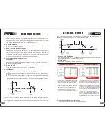
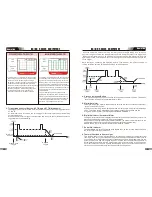
1.Gas Pre-Flow
V241: Absolute setting range 0.1s to 20s (0.1S increments)
V341: Absolute setting range 0.1s to 20s (0.1S increments)
This parameter operates in TIG modes only and is used to provide gas to the weld zone
used to dramatically reduce weld porosity at the start of a weld.
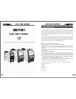
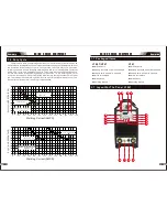
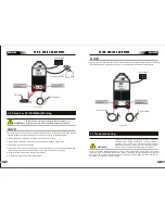
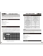
2.4 Control Panel
17. Positive Welding Terminal
Positive Welding Terminal. Welding current flows from the Power Source via heavy
duty bayonet type terminals. It is essential, however, that the male plug is inserted
and turned securely to achieve a sound electrical connection.
18. 5 Pin Control Socket
The 5 pin receptacle is used to connect a trigger switch or remote control to the welding
Power Source circuitry:
To make connections, align keyway, insert plug, and rotate threaded collar fully clockwise.
20. Shielding Gas Outlet
The Shielding Gas Outlet located on the front panel is a fast connection of a suitable
TIG Torch.
19. Negative Welding Terminal
Negative Welding Terminal. Welding current flows from the Power Source via heavy
duty bayonet type terminals. It is essential, however, that the male plug is inserted
and turned securely to achieve a sound electrical connection.
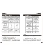
AC Frequenz
Wave Balance
Remote
ARC Hotstart
ARC Start Time
Arcforce Correction
AMP%
sec
AMP
%
HZ
sec AMP%
sec
AMP%
sec
%
1
2
3
4
6
5
7
11
12
8
9
10
13
14
2.Initial Current
V241:
The main current Setting range 10AMP to 200AMP
This parameter operates in (4T) TIG modes only and is used to set the start current for TIG.
The Start Current remains on until the torch trigger switch is released after it has been
depressed.
Note: The maximum initial current available will be limited to the set value of the base
current.
3.Up Slope
Setting ranges :0.1S-10S (0.1S increments)
This parameter operates in (2T and 4T) TIG modes only and is used to set the time for the
weld current to ramp up, after the torch trigger switch has been pressed then released,
from Initial Current to High or base current.
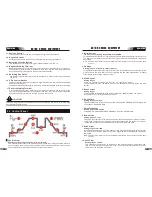
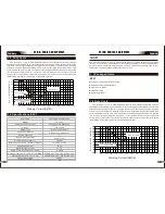
4.Peak Current
Setting ranges
V241:10
-
200A
(
DC TIG
and
AC
HF
TIG
),
10
-
200A
(
Stick
mode
)
V341:10
-
300A
(
DC TIG
and
AC
HF
TIG
),
30
-
300A
(
Stick
mode
)
This parameter sets the TIG WELD current. This parameter also sets the STICK weld
current.
5.Base Current
Setting ranges
V241:10AMP to 200AMP (DC TIG mode), 10AMP to 200AMP (AC HF TIG mode)
V341:10AMP to 300AMP (DC TIG mode), 10AMP to 300AMP (AC HF TIG mode)
Secondary current (TIG)/pulse pause current.
23
22
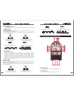
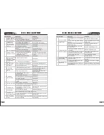
9. JOB and SAVE
You can press JOB to select the memory records that you have saved before from 1-9.
For the new setting of present base current Amps ,just press SAVE.
10. Programming Parameter Indicators
These indicator lights will illuminate when programming.
11. HF Button
Press and hold the HF button to purge the gas line in LIFT TIG and HF TIG modes. To HF
the shielding gas line in LIFT TIG and HF TIG modes press the HF button and release.
12. Mode Button
Press the MODE button to toggle AC and DC output in LIFT TIG, HF TIG and STICK.
13. Forward Programming Button
Pressing this button will advance to the next step in the programming sequence.
14. Back Programming Button
Pressing this button will go back to the previous step in the programming sequence.
15. Positive Control
The Positive button is used to plus selected in Programming sequence..
16. Negative Control
The Negative button is used to minus selected in Programming sequence..
CAUTION
V341:
The main current Setting range 10AMP to 300AMP
prior to striking the arc, once the torch trigger switch has been pressed. This control is


