42
43
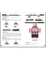
2.3 Layout For The Panel E301/E401
11
22
3
4
9
5
7
6
8
10
1. Power Indicator
The green power indicator will be illuminated when the welder is turned ON and indicates
the presence of power.
WARNING
DO NOT TOUCH the electrode wire while it is being fed through the system. The electrode
wire will be at welding voltage potential.
3.Prevent Electric Shock
The VRD button on the front panel is illuminated when pressing the VRD indicator, at the
same time the no-load voltage is lower than 15V and the output terminal is not harmful
to the human body.When the button is pressed again, the VRD indicator light goes out,
and the output is now at 71V.
Operation
STICK
SERIES
EQUIPMENT
STICK
SERIES
EQUIPMENT
2. Thermal Overload Indicator Light
This welding power source is protected by a self resetting thermostat. The indicator will
illuminate if the duty cycle of the power source has been exceeded. Should the thermal
overload indicator illuminate the output of the power source will be disabled. Once the
power source cools down this light will go OFF and the over temperature condition will
automatically reset. Note that the mains power switch should remain in the on position
such that the fan continues to operate thus allowing the unit to cool sufficiently. Do not
switch the unit off should a thermal overload condition be present.
5.Negative Control
The negative control is used to minus setting parameter for selected function from 6.
6.Selecting Function Button
Press and release this button to change the selected weld functions mode from welding
current to hotstart to start time to ARC Force from the digital display.
7.Positive Control
The positive control is used to plus setting parameter for selected function from 6.
8. Negative Welding Output Terminal
The negative welding terminal is used to connect the welding output of the power source
to the appropriate welding accessory such as electrode holder. It is essential, however,
that the male plug is inserted and turned securely to achieve a sound electrical
connection.
9. Shielding Gas Outletl
The Shielding Gas Outlet located on the front panel is a fast connection of a suitable TIG
Torch.
10. 5 Pin Control Socket
The 5 pin receptacle is used to connect a trigger switch or remote control to the welding
Power Source circuitry.
To make connections, align keyway, insert plug, and rotate threaded collar fully clockwise.
11. Positive Welding Output Terminal
The positive welding terminal is used to connect the welding output of the power source
to the appropriate welding accessory such as earth clamp. It is essential, however, that
the male plug is inserted and turned securely to achieve a sound electrical connection.
CAUTION
Loose welding terminal connections can cause overheating and result in the male plug
being fused in the bayonet terminal.
3.Weld Process Selection Button
Press and release this button to change the selected weld process mode from LIFT TIG
to STICK. The weld process will change to the next process in the sequence each time
to identify LIFT TIG or STICK process mode.
4.Digital Display
The digital meter is used to display the pre-set (preview) amperage for welding, the
preset parameters in Hot start, start time amd Arc force and actual welding amperage of
the power source when welding.
Operation
the button is pressed and released. The green indicators next to the button will illuminate

