Vatech Green X Installation Manual Download Page 35

3. Before the Installation 

Green X / X18


(Model: PHT-75CHS) Installation Manual                                     27 

En

glis

3.3 

Unpacking  the X-ray Unit 

The X-ray unit, PC, and accessories are delivered in the main box. The main box and 

foams from the inside of the box can be recycled. Unpack the main box following the 

instructions in 

3.3.1 Main Box

.   


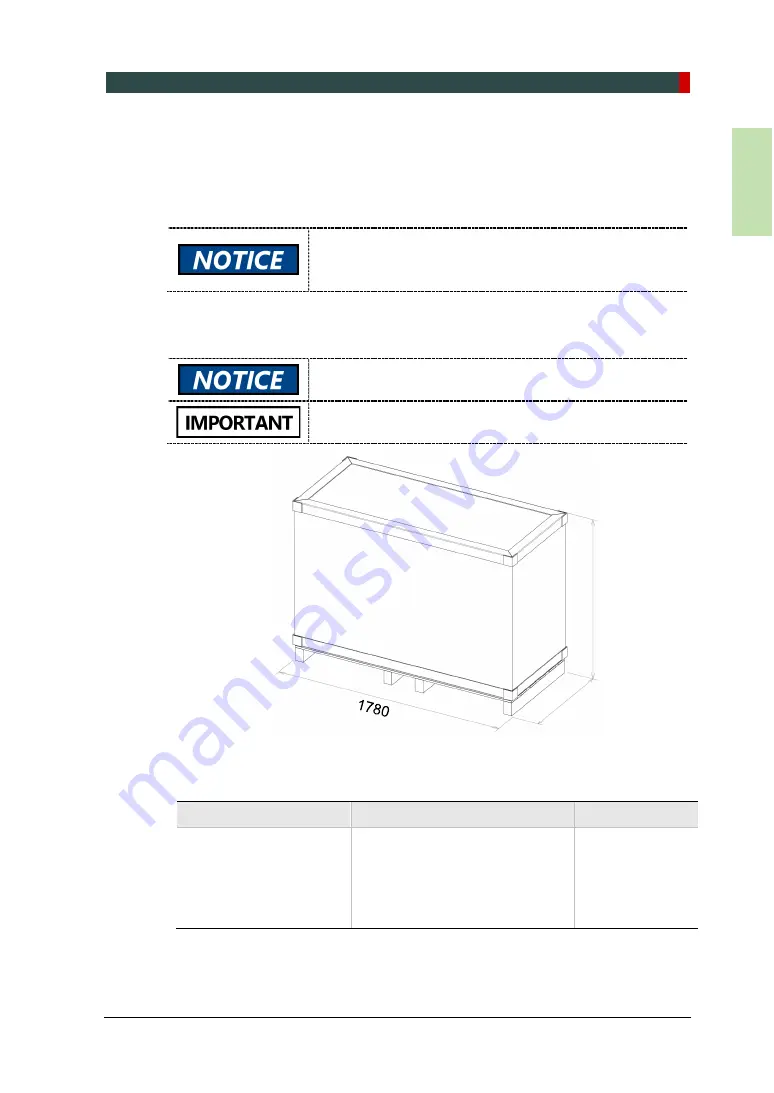
3.3.1  Main Box (Box no.1)   


Component 

Size (mm / inch) 

Weight (kg/lbs.) 

  Column and Rotating 

unit Assembly 

  Accessories and Parts 

  PC System (Optional) 

  Monitor (Optional) 

1780 (L) x 780 (W) x 1000 (H)   

/ 70.1" (L) x 30.7" (W) x 39.4" (H) 

221 / 487 


After unpacking the X-ray unit, return the main box to your 

VATECH service representative or dispose of the box 

following the recycling guide in your country. 


The edges of the main box may be sharp. Wear gloves 

when opening the box


Two persons are recommended when handling the main 

box.   

1000 

780 

Summary of Contents for Green X

Page 1: ...Installation manual Model PHT 75CHS Version 1 10 English...

Page 2: ......

Page 3: ...e subject to change without notice justification or notification of the persons concerned since the Green X X18 is in steady improvement VATECH Co Ltd manufacturer reserves intellectual property right...

Page 4: ...andling the equipment An authorized technician must install the equipment following the instructions in the installation manual Install the equipment on a flat surface to avoid injury and property dam...

Page 5: ...l Requirement 12 2 4 Installing Exposure Switch 13 2 5 Installation Versions 15 2 6 Installing the Warning Lamp and Door Interlock Switch 23 2 7 Installing the Emergency Stop Switch 23 3 Before the In...

Page 6: ...Bolts 72 5 6 Leveling the Equipment 73 5 7 Attaching the X ray Unit to the Wall 76 6 Finalizing the X ray Unit Installation 77 6 1 Attaching Lower Column and Base Cover 77 6 2 Mounting the Chinrest a...

Page 7: ...nt i Console 113 10 Technical Specifications 127 10 1 Mechanical Specifications 127 10 2 Drawing Dimensions 129 10 3 Electrical Specifications 133 10 4 Environmental Specifications 134 Appendix 1 A In...

Page 8: ......

Page 9: ...ditions according to the user manual PC software is properly used according to the manufacturer s installation and user manual 1 2 Customer s Responsibility Site planning and preparation are the respo...

Page 10: ...age to the equipment WARNING Indicates that a specific hazard can cause Severe personal injury to the operator and patient Substantial property damage CAUTION Indicates that a potential hazard can cau...

Page 11: ...or hold the sensor or tube head areas when moving installing or operating the equipment Do not step on the base when installing or operating the equipment Do not use the electric drill to tighten bolt...

Page 12: ...Manual When transporting the equipment hold the handles in marked locations Three installers are required for safe installation Check the location of the emergency stop switch as indicated below Check...

Page 13: ...perform the appropriate procedures therein If the equipment has been stored at temperatures below 10 50 for more than a couple of hours allow the equipment to reach room temperature before applying m...

Page 14: ...2002 It is strongly recommended that a UPS be installed simultaneously with the equipment The equipment PC and all peripheral devices must be well grounded This equipment complies with the following...

Page 15: ...connected to the Main Power Switch Main Power Switch Alternate current Label Type B Applied Equipment IEC 60601 1 Degree of protection against leakage current and electric shock Class 1 equipment Labe...

Page 16: ...the operator and the operator should be as about the patient as possible This equipment must not be installed on thick carpets for stability reasons Anti static floor materials must be used around th...

Page 17: ...2 Pre Installation Requirement Green X X18 Model PHT 75CHS Installation Manual 9 English With CEPH Unit optional 2 500 L x 2 500 mm W or wider...

Page 18: ...2 Pre Installation Requirement 10 Green X X18 Model PHT 75CHS Installation Manual Ceiling Height 2 700 mm H or higher...

Page 19: ...of the Entrance The X ray room door must have a clearance of more than 800 mm 31 5 wide Floor Area The floor of the X ray room must be stable and level for system balance The floor must be able to su...

Page 20: ...ovisions specified in IEC 60364 the 2nd edition 2006 Both PC and equipment must use the same power line if connected to an MPSO Whenever not possible use different power outlets for each device If a m...

Page 21: ...ere are three options for installation depending on the site s configuration Nevertheless the 2nd option is preferred Option No 1 The user operates the Exposure Switch from inside the X ray room Optio...

Page 22: ...nstallation Requirement 14 Green X X18 Model PHT 75CHS Installation Manual Option No 3 The 3rd party Exposure Switch not VATECH s is used on the customers demand For this scenario see Appendix D for d...

Page 23: ...2 Pre Installation Requirement Green X X18 Model PHT 75CHS Installation Manual 15 English 2 5 Installation Versions 2 5 1 Green X Base Stand Type With CEPH unit...

Page 24: ...2 Pre Installation Requirement 16 Green X X18 Model PHT 75CHS Installation Manual Base Stand Type Without CEPH unit...

Page 25: ...2 Pre Installation Requirement Green X X18 Model PHT 75CHS Installation Manual 17 English Wall Mount Type With CEPH unit...

Page 26: ...2 Pre Installation Requirement 18 Green X X18 Model PHT 75CHS Installation Manual Wall Mount Type Without CEPH unit...

Page 27: ...2 Pre Installation Requirement Green X X18 Model PHT 75CHS Installation Manual 19 English 2 5 2 Green X18 Base Stand Type With CEPH unit...

Page 28: ...2 Pre Installation Requirement 20 Green X X18 Model PHT 75CHS Installation Manual Base Stand Type Without CEPH unit...

Page 29: ...2 Pre Installation Requirement Green X X18 Model PHT 75CHS Installation Manual 21 English Wall Mount Type With CEPH unit...

Page 30: ...2 Pre Installation Requirement 22 Green X X18 Model PHT 75CHS Installation Manual Wall Mount Type Without CEPH unit...

Page 31: ...is energized The warning lamp and door interlock switch are not included with the equipment The warning lamp and the door interlock switch must be installed by a qualified technician 2 7 Installing t...

Page 32: ...he list below before installing the equipment Item Figure Size Wrench Set 1 5 mm 10 mm 0 06 0 4 T shaped Hex Wrench 6 mm 10 mm 0 24 0 4 Hex Wrench w Handle 6 mm 10 mm 0 24 0 4 Ratchet Wrench Tips 3 mm...

Page 33: ...for Wall Mount type 5 m Marker Pen thick tip for Wall Mount type N A Hammer For Wall Mount type N A Multimeter N A Hammer Drill for Wall Mount type L 200 mm 7 9 Transport Dolly N A Go to checklist no...

Page 34: ...damage during the transportations the watches turn red If the shock or tilt watch has turned red do not open the box and contact the nearest VATECH representative in your area The shock and tilt watc...

Page 35: ...ox 3 3 1 Main Box Box no 1 Component Size mm inch Weight kg lbs Column and Rotating unit Assembly Accessories and Parts PC System Optional Monitor Optional 1780 L x 780 W x 1000 H 70 1 L x 30 7 W x 39...

Page 36: ...reen X X18 Model PHT 75CHS Installation Manual To open the main box 1 Move the main box close to the installation site 2 Remove the strapping bands around the box and lift the top cover 3 Remove the s...

Page 37: ...18 Model PHT 75CHS Installation Manual 29 English 4 Remove the plastic cover with a cutter When one installer removes the side cover another must hold the box to prevent falling 5 Remove foams and tak...

Page 38: ...3 Before the Installation 30 Green X X18 Model PHT 75CHS Installation Manual 3 3 2 CEPH Box Optional The CEPH box is provided for customers who purchased the CEPH option...

Page 39: ...e column to attach it to the foam 2 Grab the handles and lift the X ray unit main unit from the pallet 3 Place the X ray unit with EPS Main Base on a transport dolly and carry the unit to the installa...

Page 40: ...3 Before the Installation 32 Green X X18 Model PHT 75CHS Installation Manual Transportation Example...

Page 41: ...3 Before the Installation Green X X18 Model PHT 75CHS Installation Manual 33 English 3 5 Checking the Parts and Accessories 3 5 1 Accessories Box 1 2 Overview...

Page 42: ...nual 1 n a Yes No 2D Viewer Manual 1 For EzDent i Yes No 3D Viewer Manual 1 For Ez3D i Yes No Installation USB n a 1 n a Yes No 3D Viewer License Key n a 1 For Ez3D i Yes No 2 Exposure Switch n a 1 n...

Page 43: ...Blank Intentionally 11 Sanitary Vinyl Cover For Normal Bite 1 n a Yes No 12 Bite Normal 1 n a Yes No Deep 1 Deep Bite is provided for Asian countries only Yes No Special A 1 n a Yes No Special B 1 n...

Page 44: ...Yes No 21 Frame Grabber System Optic Cable 1 One additional fiber optic cable is required when SC type is installed Yes No FTG Card or LEG Card 1 n a Yes No 22 Column Bracket n a 1 n a Yes No Model Sc...

Page 45: ...M8 x 15 4 n a Yes No 30 Set Screw M10 x 20 4 n a Yes No 31 Wall Plate n a 1 n a Yes No Terminal Block 3 Pole n a 1 n a Yes No 32 Wall mount cap Silicone 12 n a Yes No 33 UP DOWN Switch n a 1 Optional...

Page 46: ...rete Yes No 35 Wrench Bolt M8 x 25 2 n a Yes No Nut M8 2 n a Yes No 36 Wall Bracket Rear n a 1 n a Yes No Wood Wall Bracket n a For the U S only Yes No Vertical Cap n a 1 For PANO only Yes No 3 5 2 2...

Page 47: ...h 4 Installing the X ray Unit Base Stand Type 4 1 Attaching the Base to the X ray Unit If you are installing the X ray unit on a concrete floor first complete the steps in 4 4 1 Concrete Floor To atta...

Page 48: ...en X X18 Model PHT 75CHS Installation Manual 2 Put two wrench bolts into the holes on the bottom of the column unit Required Tool Allen Wrench 6 mm 0 24 Parts and Accessory Wrench Bolt M8 x 35 2 pcs P...

Page 49: ...ray Unit Base Stand Type Green X X18 Model PHT 75CHS Installation Manual 41 English 3 Install the base to the two bolt mount The Base after installation to the two bolt mount Hold the base unit to ke...

Page 50: ...d Type 42 Green X X18 Model PHT 75CHS Installation Manual 4 Tighten three wrench bolts on the underside of the base Required Tool Allen Wrench 6 mm 0 24 Parts and Accessory Wrench Bolt M10 x 25 w Spri...

Page 51: ...Green X X18 Model PHT 75CHS Installation Manual 43 English 5 Grab the upper carrying handle and lift the equipment slowly Clear the cables from the installation site before lifting the equipment to pr...

Page 52: ...l 6 Tighten three wrench bolts in the column s backside to attach the base Required Tool Allen Wrench 6 mm 0 24 Parts and Accessory Wrench Bolt M10 x 25 w Spring and Flat Washers 3 pcs Part No 23 All...

Page 53: ...4 Installing the X ray Unit Base Stand Type Green X X18 Model PHT 75CHS Installation Manual 45 English 7 Remove the top carrying handle Required Tool Allen Wrench 6 mm 0 24...

Page 54: ...the CEPH Unit Optional To Install the CEPH unit 1 Take out the CEPH unit from the CEPH box 2 Remove the plastic wrap covering the unit and CEPH cables with a cutter 3 Attach the CEPH unit to the main...

Page 55: ...47 English 4 Fix the CEPH unit to the main unit with M8X20 wrench bolts and washers When tightening the bolt place a spirit level on the CEPH unit Required Tool Allen Wrench 6 mm 0 24 Allen Wrench 8 m...

Page 56: ...he cables as shown in the figure When you are connecting optic cables Do not bend pull or crush it Ensure that the caps of the fiber optic cable have been removed Do not touch the tip of the fiber opt...

Page 57: ...nstallation Manual 49 English 6 Place the cables inside the CEPH Arm and attach the CEPH arm cover with M3x6 flat head screws Required Tool Cross Head Screwdriver w Magnetic Tip 6 mm 0 24 Parts and Ac...

Page 58: ...nstalling wall brackets Install the wall bracket first before connecting it with the column bracket 4 3 1 For the Concrete Wall To install a wall bracket on the concrete wall 1 Prepare a wall bracket...

Page 59: ...nchor bolts following the bracket holes 5 Drill the holes following the marks Each hole must be the size of 10 5mm x 30 mm 0 41 x 1 18 6 Hammer down Fisher strong anchors into drilled holes Required T...

Page 60: ...sory Wood Wall Bracket Optional Part No 36 2 Repeat the step from 1 to 4 in the procedure for 4 3 1 Concrete Wall For wood wall the distance between the wall bracket and floor must be 3 Mark the insta...

Page 61: ...column brackets check if your equipment is fully leveled If necessary follow the procedure in 4 7 Leveling the Equipment to level the equipment 1 Attach the column bracket with M8 x 15 wrench bolts At...

Page 62: ...l 3 Connect the wall and column bracket with M8 x 25 wrench bolts Place nuts underneath the bolts and tighten them with a monkey wrench as illustrated below Required Tool Allen Wrench 6 mm 0 24 Monkey...

Page 63: ...ing the Base 4 4 1 Concrete Floor To fix the base on the concrete floor Required Tool Hammer Drill L 200 mm 7 9 Ratchet Wrench Tips 3 mm 8 mm 0 12 0 3 Hammer N A Parts and Accessory Anchor Bolt 5 16 x...

Page 64: ...nual 2 Drill holes on the floor Each hole must be 12 mm x 13 mm in depth 3 Remove the debris and clean the holes using the dust pump 4 Secure the anchor bolts with the hammer 5 Place the base Put nuts...

Page 65: ...CHS Installation Manual 57 English 4 4 2 Wooden Floor To fix the base unit on the wood floor Required Tool Hammer Drill L 200 mm 7 9 Parts and Accessory Wood Screws M12 x 70 2 pcs Part No 34 1 Put M12...

Page 66: ...stallation Manual 4 5 Connecting the Cables to the Equipment To connect the cables to the equipment 1 Connect the cables in the back of the column as shown in the figure Parts and Accessory Optic Cabl...

Page 67: ...Attach the back column cover to the column with M4X10 truss bolts Required Tool Cross Head Screwdriver w Magnetic Tip 6 mm 0 24 Parts and Accessory Truss Bolt M4 x 10 4 pcs Part No 27 When you are at...

Page 68: ...ving the Transportation Safety Bolts To remove the transportation safety bolts 1 Remove the transportation safety bolts with an Allen wrench Required Tool Allen Wrench 6 mm 0 24 2 Remove the semi clea...

Page 69: ...Manual 61 English 3 Remove the vertical top cover 4 Remove four safety bolts and two safety brackets with the tags Required Tool Allen Wrench 6 mm 0 24 Be sure not to damage the cables when removing t...

Page 70: ...nual 4 7 Leveling the X ray Unit To level the equipment using a spirit level Required Tool T shaped Hex Wrench 8 mm 0 3 Spirit Level N A 1 Prepare a spirit level 2 Turn the rotating unit clockwise so...

Page 71: ...nd Left To level the equipment right and left To obtain the accurate level place the spirit level as illustrated 1 Place the spirit level inside the vertical unit as shown in the illustration below 2...

Page 72: ...he accurate level place the spirit level as illustrated 1 Place the spirit level inside the vertical frame as shown in the illustration below 2 Use a T shaped hex wrench to adjust screws in circled lo...

Page 73: ...Stand Type Green X X18 Model PHT 75CHS Installation Manual 65 English 4 8 Connecting the Wall and Column Brackets Tighten bracket bolts with a monkey wrench as illustrated below Required Tool Allen Wr...

Page 74: ...4 Installing the X ray Unit Base Stand Type 66 Green X X18 Model PHT 75CHS Installation Manual This Page Left Blank Intentionally...

Page 75: ...en X X18 Model PHT 75CHS Installation Manual 67 English 5 Installing the X ray Unit Wall Mount Type 5 1 Installing the X ray Unit Before the installation clear the site and check if the X ray unit loc...

Page 76: ...all a wall bracket according to 4 3 Installing the Wall and Column Brackets 2 Draw six drilling marks on the floor along the plate holes Parts and Accessory Alignment Plate Part No 4 Marker N A 3 Dril...

Page 77: ...ean the drilled holes with a dust pump 5 Put anchor bolts into the holes and hammer them down Check if all bolts are secured Parts and Accessory Anchor Bolt 5 16 x 60 w Spring and Flat Washers 6 pcs P...

Page 78: ...7 Hold the upper carrying handle and place the equipment on the alignment plate When placing the equipment ensure that the holes on the bottom of the column are engaged in anchor bolts Before placing...

Page 79: ...Place a nut and washer on the head of each bolt Fasten each nut to secure the column However do not fully fasten the nut before finishing the leveling Two persons are required for step 8 When one pers...

Page 80: ...alling the CEPH Unit Optional 5 3 Installing the Wall and Column Brackets Please refer to section 4 3 Installing the Wall and Column Brackets 5 4 Connecting the Cables to the Equipment Please refer to...

Page 81: ...del PHT 75CHS Installation Manual 73 English 5 6 Leveling the Equipment To level the equipment 1 Prepare a spirit level Parts and Accessory Spirit Level N A 2 Turn the Rotating Unit clockwise so that...

Page 82: ...into each hole Tighten the screws with a T shaped hex wrench At this point do not fully fasten the screw Required Tool T shaped Hex Wrench 8 mm 0 3 Parts and Accessory Set Screw M10 x 20 4 pcs Part N...

Page 83: ...X ray Unit Wall Mount Type Green X X18 Model PHT 75CHS Installation Manual 75 English 5 Place the spirit level inside the Vertical Frame as indicated below 6 Fasten each screw as indicated below to s...

Page 84: ...he X ray Unit to the Wall To attach the X ray unit to the wall 1 Attach the X ray unit to the wall by connecting the wall and column brackets Ensure to tighten the bolts until they no longer move Requ...

Page 85: ...equipment is a wall mount type you may skip the procedures in 6 1 Follow the procedure below to attach the lower column cover to the column and the base cover to the base 1 Attach the lower column co...

Page 86: ...tion Manual 2 Attach the base cover to the base with M4x16 truss bolts Cover the bolthead with the flat and round base caps after fixing the cover Parts and Accessory Truss Bolt M4 x 16 3 pcs Part No...

Page 87: ...d the Temple Supports Mount the chinrest and temple supports after capturing a test image To mount the chinrest and the temple supports 1 Mount the chinrest and the bite Parts and Accessory Normal Chi...

Page 88: ...witch holders 6 3 1 Attaching UP DOWN Switch Holder To attach the up down switch holder Parts and Accessory UP DOWN Switch Holder 1 pc Part No 33 UP DOWN Switch Optional 1 pc Part No 33 Truss Bolt M4...

Page 89: ...ttach the exposure switch holder Parts and Accessory Exposure Switch 1 pc Part No 2 Exposure Switch Holder 1 pc Part No 2 Double Sided Sticker 1pc Part No 2 Screws M3X16 2 pcs Part No 2 1 Locate the E...

Page 90: ...round the equipment 1 Cover bolts on the wall bracket and the CEPH arm optional with wall mount caps Parts and Accessory Wall mount cap 12 pcs Part No 32 2 Attach the vertical top cover with M4x10 tru...

Page 91: ...hePC Warning System Panel Used to provide a visible indicator Light on when the equipment is irradiating X ray Exposure switc h PC w imaging and image viewer programs Warning system panel Warning lamp...

Page 92: ...make the changes to its hardware and software settings This can lead to system malfunction Item Specifications HP CPU Intel Xeon W 2223 3 6 GHz 4 Core Processor RAM 2X8GB DDR4 2400 Registered RAM HDD...

Page 93: ...HS Installation Manual 85 English 7 2 1 Add Exclusions to Windows Security Follow the steps below to add exclusions to Windows security 1 Open the Start menu and type W in the search box 2 Click the W...

Page 94: ...7 Setting up PC 86 Green X X18 Model PHT 75CHS Installation Manual 3 Click the Virus threat protection 4 Click the Virus threat protection settings...

Page 95: ...7 Setting up PC Green X X18 Model PHT 75CHS Installation Manual 87 English 5 Scroll down to Exclusions 6 Click on the link Add or remove exclusions...

Page 96: ...PC 88 Green X X18 Model PHT 75CHS Installation Manual 7 On the Exclusions page click the Add an exclusion button 8 On the Select Folder dialog type C VcaptureSW in the folder field and click Exclude...

Page 97: ...the power cord from the main outlet or PC Disregard this section in case the PC system is supplied with the equipment The peripherals have already been installed inside the PC Whenever managing the f...

Page 98: ...e from the back of the PC and wait for a while 2 Open the PC cover 3 Insert the frame grabber Part No 21 into the PCIe2 x 4 slot and lock it FTG Card or LEG Board Check the locking status between the...

Page 99: ...connection or damage to the cables Connect the regular cables for the PC keyboard mouse and video in advance The following figures and descriptions are based on the PC model Z4 from HP Parts and Acces...

Page 100: ...7 Setting up PC 92 Green X X18 Model PHT 75CHS Installation Manual 4 Confirm that the cable is connected as indicated below The illustrations may differ from the actual product...

Page 101: ...nstall programs other than the imaging acquisition program and viewer to avoid system errors Use the PC system for image acquisition only It is recommended to use a separate PC for image management Ch...

Page 102: ...firewalls can block the LAN port and local IP which causes an interruption in image acquisition and data transmission To turn off the firewall follow the steps below 1 Press the Windows icon and type...

Page 103: ...ndows to avoid unintended interruptions during the image acquisition Turn off the screen saver and optimize power options following the steps below 8 3 1 Turning off the Screen Saver To turn off the s...

Page 104: ...stem Follow the steps below to change the power options for the monitor and system 1 Press the Windows icon and type Power Options 2 Click the Power Options icon 3 Click Choose when to turn off the di...

Page 105: ...below to turn off the user account control 1 Press the Windows icon and type User account control or UAC 2 Click Change User Account Control Settings 3 Move the slider to Never Notify and click OK to...

Page 106: ...C VCaptureSW Console Software To set folder exclusions 1 Open the McAfee anti virus program and select the VirusScan 2 Right click the On Access Scan menu option and left click the Properties tab 3 S...

Page 107: ...he latest version To check this information go to the graphic card manufacturer s website Before proceeding with its installation perform a virus scan for the PC and InstallShield program with the ant...

Page 108: ...llation Manual 9 2 Software Installation Flow 9 3 Installing Image Viewer Programs Before image acquisition either EzDent i or the 3rd part s image viewer must be installed Please go to the EzDent i m...

Page 109: ...equipment 2 Insert the USB drive into the USB connector Before inserting the USB drive conduct a virus scan on your PC The USB drive provided contains the InstallShield installation information Before...

Page 110: ...n Manual 5 Check if Green X or Green X18 is selected and click Next 6 Check if all modality options are selected If your equipment does not include the CEPH feature uncheck CEPH and click Next 7 Check...

Page 111: ...Green X X18 Model PHT 75CHS Installation Manual 103 English 8 Check if the WidePano is selected for the PANO sensor type and click Next 9 Optional Check if the WideCEPH is selected for the CEPH senso...

Page 112: ...quipment The same COM port must be used for both PC and equipment COM port selection varies by equipment Ensure that both PC and equipment share the same COM port 11 Select a language and click Next 1...

Page 113: ...HT 75CHS Installation Manual 105 English 13 Select a connection option for CBCT modality and click Next 14 Check if the selected options are correct then click Next When the AutoSave is checked the ac...

Page 114: ...allation Manual 15 Select the component you want to install on your PC 16 Confirm all information displayed in the Ready to Install window If necessary click Back to return to and change the previous...

Page 115: ...en X X18 Model PHT 75CHS Installation Manual 107 English 9 4 1 Installing the DirectX Follow the steps below to install the Direct X 1 Select I accept the agreement and click Next 2 Click Next to down...

Page 116: ...9 Installing Software 108 Green X X18 Model PHT 75CHS Installation Manual 3 Click Finish to complete the installation...

Page 117: ...g the Frame Grabber Virtual Serial the grabber driver installation starts after the direct X setup The following sections explain how to set up Flectron and Leon Grabber 9 4 2 1 Flectron Grabber To In...

Page 118: ...et a different destination folder 4 When the dialog box below appears check Reboot Now and click Finish If you cannot reboot your PC at the moment check I want to reboot later manually then click Fini...

Page 119: ...l 111 English 9 4 2 2 Leon Grabber To install the Leon grabber 1 Select a language and press OK 2 Press the V Grabber s Install button 3 After installation the V Grabber Installation Program dialog bo...

Page 120: ...l_Log txt on the desktop 2 Open it to check the file You can find out that all components are installed 3 Go to section 9 5 Setting up the User Information 9 4 5 Uninstalling Software To uninstall the...

Page 121: ...ip the sections from 9 5 1 to 9 5 3 Start EzDent i as an administrator to configure the program 9 5 1 Linking EzDent i to the Console Software One time Linking If EzDent i is installed as your image v...

Page 122: ...Manual 3 Select Acquisition from the setting options 4 Select Console Program In the console program tab check Console Program Path C VCaptureSW exe VCaptureSW exe Capture Message Green X Green X18 C...

Page 123: ...9 Installing Software Green X X18 Model PHT 75CHS Installation Manual 115 English 5 Click OK and restart your PC to apply the new setting...

Page 124: ...record with EzDent i For the features not explained in this section go to the EzDent i user manual 1 On the main menu page select PATIENT then click 2 After clicking a dialog box pops up Fill out the...

Page 125: ...n EzDent i 1 Click the ACQUISITION tab The imaging mode selection menu appear s in the left pane see below The imaging mode selection menu may differ due to your equipment s option CEPH or non CEPH or...

Page 126: ...5 4 Setting the Console Software Parameters To configure parameters for the console software The following information should be entered by the user requirements 1 Click from the console software s m...

Page 127: ...a language English is set as a default language If you want to change the setting click and select a new language from a dropdown list Click Machine set 5 Go to Language Option English is set as a def...

Page 128: ...fault equipment s brand name and text size are displayed as shown in the following figure 8 In the DAP check that the default DAP Level and DAP Unit are displayed as shown in the following figure 9 Cl...

Page 129: ...10 In the Patient Information Setting configure the Link Type File Path and File Name as shown the below 11 In the Link Information Setting configure the Link Type and File Extension as below Fields...

Page 130: ...een X X18 Model PHT 75CHS Installation Manual 12 Click on the Sensor Default tab and configure the user defined parameters The default features can be modified according to the user s requirements 13...

Page 131: ...1 Go to the General tab on the control panel page 2 Check Serial and set serial port and baud rate as below 3 In the Networking option enable the Serial checkbox set serial port and baud rate as illus...

Page 132: ...and PKEN_0000 to exit the packing mode Now note that the equipment is out of the packing mode Use the command PKEN_0001 to re enter the packing mode 6 Click Exit and terminate the Control Panel 7 Impo...

Page 133: ...Mode Division 0000 CT PANO Music Different for each mode 0001 CT PANO Music Same for each mode 0002 Default CT PANO Beep Same for each mode Send the command by the command specification in the table...

Page 134: ...ftware 126 Green X X18 Model PHT 75CHS Installation Manual 9 5 7 Finalizing the Parameter Settings To finalize the parameter settings 1 Click Exit and close the control panel page 2 Exit the imaging p...

Page 135: ...Weight unit kg lb Item Description Green X Without CEPH 160 6 kg 354 1 lbs without Base 217 0 kg 478 4 lbs with Base With CEPH 190 8 kg 420 6 lbs without Base 247 2 kg 545 0 lbs with Base Green X18 Wi...

Page 136: ...800 mm 31 50 Installation type Base Stand Wall Mount Default Wall Mount type Packing Box Organization Main Box CEPH Box Optional Base Box Optional Green X18 Total Height Without Base Max 2315 4 mm 91...

Page 137: ...10 Technical Specifications Green X X18 Model PHT 75CHS Installation Manual 129 English 10 2 Drawing Dimensions Green X With Base unit mm inch View With CEPH Without CEPH Top With Base Front With Base...

Page 138: ...10 Technical Specifications 130 Green X X18 Model PHT 75CHS Installation Manual Green X Without Base unit mm inch View With CEPH Without CEPH Top Without Base Front Without Base...

Page 139: ...10 Technical Specifications Green X X18 Model PHT 75CHS Installation Manual 131 English Green X18 With Base unit mm inch View With CEPH Without CEPH Top With Base Front With Base...

Page 140: ...10 Technical Specifications 132 Green X X18 Model PHT 75CHS Installation Manual Green X18 Without Base unit mm inch View With CEPH Without CEPH Top Without Base Front Without Base...

Page 141: ...Accuracy Tube Voltage kVp 10 Tube Current mA 20 Exposure Time s 5 50 ms The input line voltage depends on the local electrical distribution system Allowable input voltage fluctuation requirement 10 M...

Page 142: ...nstallation Manual 10 4 Environmental Specifications Item Description During Operation Temperature 10 35 Relative humidity 30 75 Atmospheric pressure 860 1060 hPa Transport and Storage Temperature 10...

Page 143: ...10 Technical Specifications Green X X18 Model PHT 75CHS Installation Manual 135 English This Page Intentionally Left Blank...

Page 144: ......

Page 145: ...hall be agreed upon with the local radiation protection advisor RPA customer A fluorescent lamp shall not be used in the X rays on sign The customer shall be responsible for the proper installations o...

Page 146: ...Appendix A 2 Green X X18 Model PHT 75CHS Installation Manual Schematic Diagram Components Supplied...

Page 147: ...k cable 5 m 198 Warning lamp 1 m 40 Power source cable 1 m 40 To install the warning lamb and door interlock switch 1 Prepare a warning system panel 2 Install the panel at a proper height according to...

Page 148: ...stall the switch in a location where the user can easily access in an emergency but cannot push it by mistake The switch must be a mistake proof type The switch is not supplied The switch must be inst...

Page 149: ...X X18 Model PHT 75CHS Installation Manual A 5 English C Limiting the Column Height To limit the column height 1 Measure your ceiling height Hceiling 2 Use the up down switch to set the equipment to a...

Page 150: ...n X X18 Model PHT 75CHS Installation Manual Removing the Column Cover To remove the column cover 1 Remove fixing bolts as in the image below 2 Disassemble the side cover If necessary also disassemble...

Page 151: ...del PHT 75CHS Installation Manual A 7 English 3 Loosen the screw to adjust the height Caution Do not remove the screws completely at this stage 4 Tighten the screws again 5 Assemble the cover in rever...

Page 152: ...f the equipment when the column is fully extended d Hceiling HMax Hceiling 2336 mm Example height The height of the equipment without Base Ex If Hceiling is 2200 mm the Hscrew height value is calculat...

Page 153: ...To connect the third party exposure switch to VATECH equipment 1 Cut the exposure switch cable provided with the equipment 2 Rewire the cable according to the schematic diagram below 3 Check the wiri...

Page 154: ...ng PC BIOS Settings HP PC BIOS Setup PC Model HP Z4 PC BIOS default Main Menu Sub1 Menu Sub2 Menu Setup Value Advanced Power Options Runtime Power Management Disable Advanced Power Options Idle Power...

Page 155: ...A 11 English F Installation Checklist 1 General Information Customer Information about the Equipment Purchaser Name of Clinic or Hospital Address Phone E Mail Website Dealer Information about the Equi...

Page 156: ...f Installation Date of installation Model Serial No 3 System Delivery to Site Yes No Did you review and identify the delivery route and method for equipment in advance Is the freight elevator availabl...

Page 157: ...tedcircuit Does the electrical input condition to the installationsite meet the MEIGaN requirements Is the local Network IP address of the clinic 192 168 33 xx Is a compressor or air conditioner sucti...

Page 158: ...atches or broken surface equipment Were all accessories and cases included in the box Have you read the installation manual out in its entirety before starting the installation Did the installer take...

Page 159: ...les especially optic cables are not coiled too much Did the installers follow the manual while installing the equipment Did the installers make sure not to touch or compress sensors while installing D...

Page 160: ...ssage audible during system initialization after turning on the system Does the LED on the front of the equipment turn green Does the Up Down switch work properly 7 Software Compatibility Yes No Is An...

Page 161: ...t protection w 20A Is internal line impedance checked Zinput 0 5 Do equipment and PC use the same dedicatedcircuit 9 Network Requirements Yes No Is a network configured with 1 Gbit s of CAT5 Is the eq...

Page 162: ...Appendix A 18 Green X X18 Model PHT 75CHS Installation Manual This Page Left Blank Intentionally...

Page 163: ...any alterations that may be required due to technical improvement For the most current information contact your VATECH representative Tel 82 1588 9510 Email gcs vatech co kr Website www vatech com He...

Page 164: ...com...

Reviews: