background image

959D Leak Detector 

2-2

DRAFT 

9/13/02

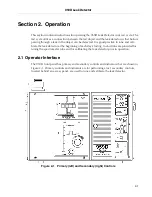
2.1.1 Primary Controls and Indicators

The primary controls are shown in the front panel drawing of Figure 2-2.

\

Figure 2-2 959D Primary Controls and Indicators

VENT button

Lights when pressed to vent the test port to atmosphere.

HI VAC OK

Green LED lights when operational vacuum is reached in the spec-
trometer tube. Remains lit until vacuum condition is lost.

PRESSURE 
indicator

Horizontal bar graph that displays test port pressure in milliTorr.

FIL Indicator 

Green LED indicating that the spectrometer tube filament is turned 
on and emission is present.

OVER range

LED at top of pressure bar graph indicates an over-scale condition. 
See Section 2.4.2 “Out-of-Range Situations” on page 2-10 for 
details.

LEAK RATE display Bar graph shows leak rate of the object under test in atm cc/sec.

The mantissa (x10) is on the vertical bar graph; the exponent is 
shown in the LCD window.

TEST button

Lights when leak detector moves into 
TEST after START or when pressed 
from HOLD.

START button

This initiates test port roughing, which 
then automatically transfers into TEST.

Lights while the test port is being 
roughed down and when pressed from 
HOLD.

HOLD button

Lights when power is first applied and 
when pressed.
In HOLD, the rough valve is off and 
the test port is isolated. 
The leak detector moves into HOLD if 
spectrometer tube pressure is exces-
sive or if there is an ion source fila-
ment failure.

1

5

6

7

9

2

3 44

11

12

8

10

Summary of Contents for 959D

Page 1: ...OPERATIONS MANUAL vacuum technologies Manual No 699909745 Revision A September 2002 Model 959D Dry Leak Detector ...

Page 2: ...ry Leak Detector Contra Flow MacroTorr and TriScroll are trademarks of Varian Vacuum Technologies Apiezon is a registered trademark of M I Materials Ltd Alconox is a registered trademark of Alconox Inc Loctite and PST are registered trademarks of Loctite Corporation Scotch Brite is a trademark of 3M ...

Page 3: ... including representatives of Seller which are inconsistent or in conflict with the terms of this warranty shall not be binding upon Seller unless reduced to writing and approved by an officer of Seller Warranty Replacement and Adjustment All claims under warranty must be made promptly after occurrence of circumstances giving rise thereto and must be received within the applicable warranty period ...

Page 4: ...iated with this equip ment They must know how to recognize hazardous and potentially hazardous conditions and know how to avoid them The consequences of unskilled improper or careless opera tion of the equipment can be serious This product must only be operated and maintained by trained personnel Every operator or service person must read and thoroughly understand operation maintenance manuals and...

Page 5: ...ilated room Alcohol methanol or other solvents are irritants narcotics depressants and or carcinogens Their inhalation and or ingestion may produce serious side effects Prolonged or continued contact with the skin will result in absorption through the skin and moderate toxicity Always ensure that cleaning operations are carried out in large well ventilated rooms and wear eyeshields gloves and prot...

Page 6: ... are static sensitive devices Varian Vacuum Technologies recommends that you wear a grounding device when performing any maintenance on the 959D and especially when performing maintenance of static sensitive parts WARNING Use only the power cord that was provided with your leak detector The use of extension cords is not recommended and could result in damage to the equipment and loss of warranty T...

Page 7: ...ration of this equipment in a residential area is likely to cause harmful radio communications interference in which case the user will be required to correct the interference at his own expense Vacuum Equipment and Cleanliness Cleanliness is vital when servicing the leak detector or any vacuum equipment There are some techniques that are more important in leak detector servicing than in general v...

Page 8: ...ces on O rings that will come in contact with the spectrometer tube Do not use alcohol methanol or other solvents on O rings To do so causes deterioration and reduces the O ring s ability to hold a vacuum In allowable situations apply a small amount of Apiezon L grease and wipe the O rings shiny dry NOTE Included in the Component and Spectrometer Tube Cleaning Kit p n 670029096 VacuSolv is recomme...

Page 9: ... its field strength causing the spectrometer tube to lose sensitivity WARNING Store the ion source in a cool dry area in a tightly sealed container Wash hands thoroughly after handling the ion source and especially before smoking or eating Pumps WARNING To avoid injury use proper lifting techniques when moving pumps Your system may have pumps that require two people to move them safely WARNING The...

Page 10: ...able calibrated leak testing and verification services Courses in leak detection including in depth operational and maintenance instruction for the 959D Contacting Varian Vacuum Technologies In the United States you can contact Varian Vacuum Technologies Customer Service and Technical Support at 1 800 8VARIAN Internet users Send email to Customer Service and Technical Support at vpl customer suppo...

Page 11: ...Automatic Valve Operation for Large Volume Leak Checks 1 11 1 6 3 Main Electronics Assembly and Circuit Boards 1 11 1 7 Specifications 1 13 Section 2 Operation 2 1 2 1 Operator Interface 2 1 2 1 1 Primary Controls and Indicators 2 2 2 1 2 Secondary Controls and Indicators 2 3 2 1 3 Rear Panel Components 2 5 2 1 4 Connecting to the Test Port 2 6 2 2 959D Startup Procedure 2 7 2 3 Changing the Audib...

Page 12: ...ource 3 6 3 4 2 Examining the Ion Source 3 10 3 4 3 Cleaning the Ground Slit Plate 3 12 3 4 4 Installing the Ion Source 3 14 3 4 5 Cleaning the Preamplifier Cavity 3 17 3 4 6 Replacing the Preamplifier 3 17 3 4 7 Installing the Spectrometer Tube 3 18 3 5 Replacement Parts 3 19 3 6 Accessories 3 19 Appendix A Introduction to Leak Detection A 1 A 1 Why Leak Testing is Necessary A 1 A 2 Classes of Le...

Page 13: ...ut and Clamp 3 7 3 5 Extracting the Spectrometer Tube 3 7 3 6 Spectrometer Tube O ring and Centering Ring 3 8 3 7 Removing Flange Cap Screws 3 8 3 8 Disengaging Flange Cap 3 9 3 9 Removing the Ion Source 3 9 3 10 Ion Source 3 10 3 11 Ion Source Cavity 3 11 3 12 Ground Slit Plate 3 12 3 13 Cleaning the Ground Slit Plate 3 13 3 14 Ground Slit Plate Properly Inserted 3 14 3 15 Replacing the Ion Sourc...

Page 14: ...itle Page 1 1 Helium Sensitivity Ranges and MDL 1 8 1 2 Valve Operating States 1 11 1 3 959D Operating Specifications 1 13 3 1 Scheduled Maintenance 3 3 3 2 As required Maintenance 3 3 3 3 959D Replacement Parts 3 19 3 4 959D Accessories 3 19 A 1 Decimal Notation A 2 ...

Page 15: ...ccessory allows the 959D to operate as a quick response high sensitivity sniffing leak detector Operation is performed using primary controls located on the front of the 959D and second ary controls located behind a locking access door The 959D front view is shown in Figure 1 1 The leak detector electronics operate the spectrometer assembly control the high vacuum pump control the valve block and ...

Page 16: ...959D Leak Detector 1 2 D R A F T 9 1 3 0 2 Figure 1 1 Model 959D Leak Detector ...

Page 17: ...MacroTorr pump and for the TriScroll 610 Any optional equipment purchased 1 2 1 Unpacking Instructions To unpack the 959D 1 Inspect the container for evidence of damage in shipment Do not discard any evidence of rough handling 2 Report without delay any damage to both the carrier and to Varian Vacuum Technologies Customer Service at 1 800 8VARIAN 3 Carefully remove the outer shipping container 4 I...

Page 18: ...3 Lift the rear of the unit and roll it on the front casters until it is clear of the skid 4 Gently lower the rear end onto the floor Method 2 1 Using the brace removed in step 7 of Section 1 2 1 Unpacking Instructions as a lever carefully raise the front edge of the skid between 1 and 2 inches 2 While a helper holds the leak detector against the back brace unscrew and remove the front two Skid Ma...

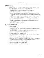
Page 19: ...pletely mobile and can be moved quickly and conve niently around an entire plant or other facility on short notice Additional ventilation requirements for your specific application as discussed in Section 1 4 3 Clean Room Use of the Leak Detector must also be provided at this point CAUTION Allow at least a 4 inches of clearance to ensure that air flows freely around the leak detector Do not block ...

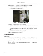
Page 20: ...ehind the access door on the leak detector is OFF down The power switch on the AC input power strip located at the bottom of the cart is OFF An appropriately grounded receptacle is available Plug the AC power cable into the receptacle 1 4 2 Gas Requirements 1 4 2 1 Helium For testing products or leak checking with the 959D use welding grade helium in a stan dard cylinder with a pressure regulating...

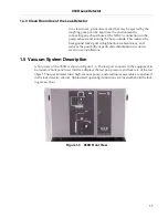
Page 21: ...nt areas and reduces the possibility of particulate distribution in sensitive clean room installations 1 5 Vacuum System Description A front view of the 959D is shown in Figure 1 3 The test port connects to the equipment to be tested A front panel user interface displays the test port pressure and leak rate of the test object The spectrometer tube high vacuum pump and electronics assembly are encl...

Page 22: ...consists of a dual thoriated iridium filament ion source a preamplifier and a magnet assembly High vacuum pump The 959D achieves high vacuum for the spectrometer tube by use of Varian s V70 Turbo or V70D MacroTorr pumps Use the V70 Turbo turbomolecular pump for best helium sensitivity Use the V70D MacroTorr for operation of the leak detector with high test port pressures up to 200 mTorr The helium...

Page 23: ...ponse high sensitivity sniffing mode operations Stereo headphones that can be connected to the remote speaker jack model Switchcraft 260 jack located on the rear panel The speaker with internal impedance between 4 Ω and 8 Ω and a 5 watt minimum power capability can be up to 50 feet 15 24 m from the leak detector This jack can also drive a set of headphones The internal stereo loudspeaker is disabl...

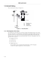
Page 24: ...onics are responsible for automatically sequencing the testing operation as described in the next section The front panel operating buttons display the current leak detector mode as well as function as operation buttons All valve coils operate at line volt age There are four valves Roughing valve V1 Test valve V2 Vent valve V3 Isolation valve V6 The V6 isolation valve is normally closed when power...

Page 25: ...ntinues indefinitely if the leak detector is left in Start mode or until the leak detector is switched into Test mode If the test port pressure rises to between 125 mTorr and 300 mTorr overpressure protection automatically sets the leak detector into Hold mode The normal operating states of the valves are shown in Table 1 2 1 6 3 Main Electronics Assembly and Circuit Boards The main electronics as...

Page 26: ...es and controls the spectrometer tube Logic board The logic board controls the front panel operation buttons Turbo Pump Controller board The turbo pump controller board powers the V70 Turbo pump and the V70D MacroTorr pump It is a microprocessor controlled solid state frequency converter with self protection features The pump controller incorporates all the facilities required for auto matic opera...

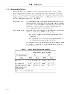
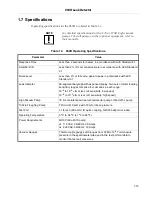
Page 27: ...r 50 segment bar graph with exponent display Two sets of direct reading sensitivity ranges comprise four decades in each range 10 9 to 10 6 atm cc sec HI sensitivity low speed 10 8 to 10 5 atm cc sec LO sensitivity high speed High Vacuum Pump 70 l m maintenance free turbomolecular pump or MacroTorr pump TriScroll roughing Pump TriScroll 610 pump with 10 mTorr base pressure Test Port 1 1 8 inch 28 ...

Page 28: ...959D Leak Detector This page intentionally left blank D R A F T 9 1 3 0 2 ...

Page 29: ... cali brate the leak detector at the beginning of each day s testing Instructions are provided for tuning the spectrometer tube and for calibrating the leak detector prior to operation 2 1 Operator Interface The 959D front panel has primary and secondary controls and indicators that are shown in Figure 2 1 Primary controls and indicators are for performing a test secondary controls located behind ...

Page 30: ...ssure bar graph indicates an over scale condition See Section 2 4 2 Out of Range Situations on page 2 10 for details LEAK RATE display Bar graph shows leak rate of the object under test in atm cc sec The mantissa x10 is on the vertical bar graph the exponent is shown in the LCD window TEST button Lights when leak detector moves into TEST after START or when pressed from HOLD START button This init...

Page 31: ... 1 on page 1 8 list the range values 2 1 2 Secondary Controls and Indicators The secondary controls are on the front of the 959D behind a keyed access panel The par tially open panel is shown in Figure 2 3 Figure 2 3 Opening the Access Panel The secondary control panel is shown in detail in Figure 2 4 on page 2 4 The leak detector is tuned and calibrated at the factory prior to shipment During nor...

Page 32: ...ce filaments 1 and 2 ON AUTO or OFF toggle switch ON AUTO provides filament activation when HI VAC OK is achieved OFF dis ables filament emission EMIS Adjusts the ion source emission voltage when tuning the spectrometer tube AUDIO VOL outer ring Controls the volume of internal speaker external speaker or headphones THOLD inner ring Volume threshold for an alarm CAL Adjusts amplifier gain to make t...

Page 33: ...or 220 VAC power cable depending on the configuration The power configuration is factory set Phono Jack under manifold Connection for an optional loudspeaker or headphones and an optional rate meter or chart recorder Circuit Breakers The POWER circuit breaker provides AC to the leak detector and to the TriScroll 610 see Figure 1 2 on page 1 6 The MAIN POWER switch inside the front panel access doo...

Page 34: ...6428801 has twelve adapters ranging from 1 16 to 1 in diameter CAUTION To avoid contamination of the vacuum system the test port plug should be in place when the 959D is not being used for testing Figure 2 6 Vacuum Test Port To connect to the test port 1 Loosen the tightening nut to remove the test port plug 2 Place the object to be tested onto the test port and tighten the nut Reasonable hand tig...

Page 35: ...e access panel door and move the MAIN POWER switch to ON Check that the ON AUTO switch is ON The turbo pump will start 5 Set the FIL toggle to ON AUTO The HOLD button will be lit The HI VAC OK and TURBO READY indicator LEDs will light Wait until the FIL indicator lights You may have to repeat step 5 until the FIL light stays on If the filament will not light after repeated attempts the ion source ...

Page 36: ...3 Select a sensitive range using the RANGE control 4 Use the ZERO control to move the bar graph segment up scale The alarm should be audible and rise relative to the increase on the bar graph 5 If the alarm is not audible be sure that the threshold is set correctly and that the VOL is turned up 6 Return the ZERO and RANGE controls to their original positions once verification is complete 2 4 Runni...

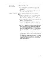
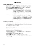
Page 37: ...es the system assumes that there is a gross leak in the test object or the system is pumping down a very large volume The system goes into HOLD to allow more time for pumpdown When the pressure drops below 250 mTorr the TEST reactivates The HOLD button illuminates for 30 seconds alternating with the START button every three minutes if the test port pressure fails to drop below 250 mTorr NOTE If th...

Page 38: ...tch arrives at its lowest setting of 1 bar and the display is still stuck at its lowest point you can assume that the system background is actu ally below any previously set zero value Refer to section 2 6 1 to re zero the leak detector 2 4 3 Testing above 200 mTorr The 959D is designed to detect very small leaks at very low pressures But the system can detect leaks at relatively high pressures gr...

Page 39: ...tion 2 5 1 Calibrating with a Calibrated Leak on page 2 11 Section 2 5 2 Use of a Capillary Type Calibrated Leak for Tuning to He on page 2 13 Section 2 5 3 Tuning the Spectrometer Tube Using a Calibrated Leak for Tuning to He on page 2 13 Section 2 5 4 Tuning the Spectrometer Tube Using a Tuning Leak on page 2 14 2 5 1 Calibrating with a Calibrated Leak Verify that startup has taken place that th...

Page 40: ...etecting helium Go to Section 2 5 3 Tuning the Spectrometer Tube Using a Calibrated Leak for Tuning to He 9 Rotate RANGE to the far left its most sensitive position 10 Slowly ZERO the 959D using the control on the primary panel If a larger adjustment is necessary first adjust COARSE ZERO on the secondary panel and then ZERO on the primary panel 11 Open the calibrated leak valve and wait about 10 s...

Page 41: ...Figure 2 4 on page 2 4 To tune the spectrometer tube using a calibrated leak 1 Perform steps 1 through 7 of the calibration procedure on page 2 11 2 Turn RANGE to the value of the exponent indicated on the calibrated leak If the bar graph display is 1 or 9 move RANGE until the bar graph displays between 1 and 9 3 Slowly adjust FOCUS for a maximum on the leak rate display It is now necessary to be ...

Page 42: ...ctrometer Tube Using a Tuning Leak The tuning leak is a specially designed adjustable needle valve in an adapter to fit the test port When the needle valve is opened such that test port pressure is 100 mTorr helium nat urally present in the atmosphere 5 parts per million enters the leak detector giving a leak rate reading of approximately 10 6 atm cc sec Since this reading is about 10 times as lar...

Page 43: ...ak rate display NOTE The ION control is a 10 turn potentiometer and normally needs to be adjusted only slightly for a maximum peak on the display When tuned to helium the outer dial on the ION control at the 12 o clock position should indicate between 2 and 8 A change in one adjustment may affect the others Therefore it may be necessary to repeat step 9 through step 12 until no significant change ...

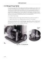
Page 44: ...in Figure 2 9 The nitrogen is introduced to the system via a port on the roughing pump from where it flows through the pump toward the leak detector and replaces and then blocks the entry of ambient helium To set up the nitrogen purge 1 Remove the plug on the nitrogen port and connect the N2 as shown in Figure 2 9 2 Adjust the flow meter to by rotating the knob at its base to 5 liters minute For m...

Page 45: ...system is warmed up tuned and calibrated and ready for testing 2 Place the test port plug in the test port and tighten the nut 3 Set RESIDUAL BACKGROUND to CHECK When this switch is in the CHECK position the leak detector is almost completely insensitive to all gases including helium 4 Move RANGE fully counterclockwise to its most sensitive position 5 Press START and wait until minimum test port p...

Page 46: ...e idle a few hours put it into standby If the leak detector is not going to be used for an extended period such as eight hours or more perform the shutdown procedure to prolong bearing life If the leak detector is to be moved to a remote location perform a complete shutdown procedure 2 8 1 Standby Perform this procedure to shut down the 959D for a period of up to 8 hours 1 Plug the test port 2 Pre...

Page 47: ...he HI VAC OK pressure indication is lit 1 Set the FIL switch to the ON AUTO position and release it This may have to be repeated several times The green FIL indicator should remain lit 2 If the filament does not light move the filament selector switch to the other filament and try to light it again 3 If the filament still does not light perform a complete shutdown wait a few minutes and then start...

Page 48: ...959D Leak Detector This page intentionally left blank D R A F T 9 1 3 0 2 ...

Page 49: ... out replacement of the ion source may be required Advice on cleaning and replacing components of the spectrometer tube can be obtained by contacting Customer Service at Varian Vacuum Technologies 3 1 Safety and Maintenance 3 1 1 AC Power WARNING Disconnect power from the 959D before performing any maintenance procedure that requires physically disconnecting any part of the system 3 1 2 Static Cha...

Page 50: ...eterioration and reduces the O ring s ability to hold a vacuum In allowable situations apply a small amount of Apiezon L grease and wipe the O rings shiny dry 3 1 5 Cleaning Kit The Varian Component and Spectrometer Tube Cleaning Kit p n 670029096 is recommended for cleaning the spectrometer tube components as well as for the fine cleaning of other parts in the leak detector s vacuum system such a...

Page 51: ...n and Tuning on page 2 11 Spectrometer tube overhaul 12 months or less depending on application Section 3 4 Cleaning or Replacing the Spectrometer Tube on page 3 5 Table 3 2 As required Maintenance Function Most Common Symptom Refer to Cleaning the Test Port Section 3 2 Cleaning the Test Port on page 3 4 Spectrometer tube cleaning Loss of sensitivity increase in background Section 3 2 Cleaning the...

Page 52: ...be removed 5 Before reusing O rings or installing new O rings wipe them down with a lint free cloth to ensure that there is no foreign matter present to impair the vacuum seal 6 Apply a small amount of Apiezon L grease and wipe the O rings shiny dry 7 Examine all parts of the test port including inside the test port Use a VacuSolv wipe to remove any dirt or foreign matter Allow parts to air dry 8 ...

Page 53: ...ometer Tube The ion source and the preamplifier require periodic inspection and cleaning After a cer tain amount of use they may also require replacement The following set of procedures covers both replacement with new components and cleaning of the existing items Although O rings can be effectively cleaned Varian recommends that all O rings be replaced whenever they have been removed from a vacuu...

Page 54: ...e VENT button Turn off the MAIN POWER switch on the front panel WARNING Disconnect power from the 959D before performing any maintenance procedure that requires physically disconnecting any part of the system Turn off the power switch on the AC power strip located at the bottom of the cart 2 Remove the top cover as described in Section 3 3 Removing the Cover on page 3 5 3 Locate and remove the con...

Page 55: ...ump Figure 3 4 Figure 3 4 Wing Nut and Clamp 5 Lift the entire spectrometer tube assembly off the turbo pump and out of the chassis as shown in Figure 3 5 Figure 3 5 Extracting the Spectrometer Tube You may have to rock the spectrometer tube gently to break the vacuum Position wingnut upward when reassembling NW 25 Clamp ...

Page 56: ... and centering ring Figure 3 6 and place them on a clean non magnetic surface Figure 3 6 Spectrometer Tube O ring and Centering Ring 7 Remove the 4 screws that hold the ion source flange cap Figure 3 7 Figure 3 7 Removing Flange Cap Screws Flange Caps Center Posts ...

Page 57: ...e images of Figure 3 8 Figure 3 8 Disengaging Flange Cap 9 If the flange cap and ion source come up together hold one hand under the ion source to catch it and then push down on the center post 10 Remove the ion source from the spectrometer tube body as shown in Figure 3 9 Figure 3 9 Removing the Ion Source Press here on Center Post Pressing Center Post Lifting Flange Cap ...

Page 58: ...ilaments They are extremely fragile Figure 3 10 Ion Source NOTE Dark carbon like deposits around the ion source filament and or a rainbow like discoloration on the inside walls of the ion source cavity indicate that the spectrometer tube has been operated at too high a pressure This can occur from a system pressure leak or transferring into test at too high a pressure VacuSolv can also be used for...

Page 59: ...ource cavity It must be replaced in exactly the same relative position If the ground slit plate or ion source cavity walls are lightly discolored remove the plate and clean using the following steps or replace it see Section 3 4 4 Installing the Ion Source on page 3 14 If the ground slit plate is highly discolored contact Varian Vacuum Technologies Customer Service at 1 800 8VARIAN Slit Alignment ...

Page 60: ... slit plate Figure 3 12 by placing a thin slotted screwdriver snug into the slot and carefully twisting and prying with the screwdriver 2 Place the ground slit plate on a clean surface Figure 3 12 Ground Slit Plate NOTE This procedure requires the use of a locking screwdriver of the type designed to grab onto the slot of a screw Ground Slit Plate ...

Page 61: ...Inspect all O rings Wipe with a lint free cloth to be sure they are free of debris CAUTION Remove O rings carefully with your fingers Do not use metal tools for this task Follow these guidelines to prevent scratching of any sealing surfaces Wipe all O rings clean with a lint free cloth before installation to assure that no foreign matter is present to impair the seal Do not use grease or use other...

Page 62: ...12 with the prongs facing up CAUTION Be sure to seat the ground slit plate firmly and in its proper orientation 2 Carefully place the ground slit plate into the cavity being sure to align the slit so that it is perpendicular to the back and front of the spectrometer tube Figure 3 14 The hole in the ground slit plate will line up with the alignment hole on the bottom of the ion source cavity Figure...

Page 63: ...rbonate gloves If you handle the ion source with bare hands wash them thoroughly and especially before smoking or eating 4 Place the O ring on the ion source as shown in Figure 3 15 Figure 3 15 Replacing the Ion Source O ring When replacing the preamplifier and ion source have the key of the center post line up perpendicular to the spectrometer tube body This alignment will happen by default for s...

Page 64: ...rce alignment pin touch the sides of the hole Figure 3 16 Ion Source Alignment Pin CAUTION A short circuit could take place at power up if the alignment pin touches the sides of the alignment hole Hold onto the O ring so that it seats properly when inserting the ion source 6 Replace the ion source flange cap so that the grooves in the depression of the flange cap line up with the legs on either si...

Page 65: ...amplifier 4 Carefully remove the preamplifier from the spectrometer tube body and place it on a clean non magnetic surface 5 Remove and discard the O ring from the preamplifier 6 Clean the preamplifier cavity if discoloration is present 3 4 6 Replacing the Preamplifier CAUTION The preamplifier is a static sensitive device Wear a grounding device while the preamplifier is being handled 1 Wipe the n...

Page 66: ... Place the centering ring and O ring against the turbo pump flange 5 Place the spectrometer tube against the centering ring then attach and fully tighten the NW 25 clamp making sure the wingnut is facing upward 6 Attach the connector plugs for the preamplifier and the ion source 7 Replace the mylar sheeting 8 Replace the cover as described in Section 3 3 Removing the Cover on page 3 5 9 Turn the l...

Page 67: ...meter Tube Assembly Exchange Program GGL9713301 Spectrometer Tube Cleaning Kit 670029096 Ground Slit Plate K3088001 V70D Turbo Pump Exchange Program Call Varian V70LP Turbo Pump Exchange Program Call Varian Table 3 4 959D Accessories Part Part Number Calibrated Leak Helium reservoir Refillable Leak 10 7 atm cc sec range F8473301 Refillable calibrated leak for evacuation sniffing use 10 5 10 6 rang...

Page 68: ...959D Leak Detector This page intentionally left blank D R A F T 9 1 3 0 2 ...

Page 69: ... general classes of leak detection Hermetic Enclosures or parts thereof These are tested to prevent entrance of contaminants or loss of fluid that would affect performance of the enclosed unit Examples include electronic devices integrated circuits sealed relays motors ring pull tab can ends and multipin feedthroughs Hermetic Systems These are tested to prevent loss of fluid or gas within Examples...

Page 70: ...d be expressed in torr liters second Conversions 1 std cc sec 0 76 torr liter sec 1 torr liter sec 1 3 std cc sec 1 std cc sec 9 7 x 10⁴ micron cubic feet per hour or practically 105 micron CFH µCFH 1 µCFH practically 10 5 std cc sec for practical purposes equal Numerical Notation Exponential System Most leak rates of commercial significance are very small fractions of atm cc sec Therefore negativ...

Page 71: ... cc sec It tests for ultrasonic sounds coming from a gas leak and for testing high pressure lines Halogen sensitive to halogen elements or compounds especially refrigerant gases This method is good to approximately 10 5 atm cc sec in most current applications but extendable to 10 9 std cc sec under some limited situations It is critically dependent on operator judgement if leaks are below 10 5 atm...

Page 72: ...g current is amplified and a leak rate bar graph indicates the presence and amount of helium A 5 2 Application as a Leak Detector A mass spectrometer leak detector consists of a spectrometer tube the electronics to operate and interpret it and a high vacuum system to maintain proper vacuum In addition means are provided for connecting a test object and a rough vacuum pump and a system of rough ing...

Page 73: ... of ceramic to metal plastic to metal seals welded soldered and brazed joints Some long path leaks are slightly smaller Diffusion of helium through glass can be as high as 10 8 std cc sec per square centimeter of surface area Variation in Leak Sizes Leaks unintentionally built in at joints during manufacture can vary from hour to hour and day to day Breathing on a 10 6 std cc sec leak provides eno...

Page 74: ...ivity with production testing capability There are three basic methods in common use A 6 1 Test Piece Evacuated The object to be tested is evacuated by the leak detector roughing pump then valved into the spectrometer vacuum system Figure A 1 and Figure A 2 The surface of the test object is then probed with a small jet of helium to locate individual leaks or surrounded by helium hooded for an over...

Page 75: ...ugh the probe and enters the leak detector thus locating the leak Sensitivity of this type of testing is limited to about 10 7 atm cc sec since most of the escaping helium diffuses into the surrounding atmosphere The sensitivity is also limited by operator technique and variation in ambient helium concentration in the vicinity of the testing An alternative to probing is to enclose the object and p...

Page 76: ...sing tube called a spectrometer tube electronics to operate the tube and a vacuum system to maintain a very high vacuum within this tube usually less than 0 1 milliTorr or about one ten millionth of ordinary atmospheric pressure In the spectrometer tube gas molecules are ionized given a positive electrical charge by bombarding them with electrons from a hot thoriated iridium filament The ions thus...

Page 77: ...d or if pressurized the chamber in which they are to be tested is rough pumped by a mechanical vacuum pump before they are connected to the spectrometer tube Figure A 5 This prevents overloading the vacuum pumping system Figure A 5 Magnetic Separation Principle ...

Page 78: ...959D Leak Detector This page intentionally left blank D R A F T 9 1 3 0 2 ...

Page 79: ...meter tube 3 18 Ion source 3 14 L Leak detection methods A 6 Already sealed A 7 Evacuated A 6 Pressurized A 7 Leak rate A 5 A 6 Leak test methods Dye penetrant A 3 Halogen A 3 Helium A 3 Radioisotope A 3 Ultrasonic A 3 Water immersion A 3 Leak testing A 1 Leak types A 1 Locate leak by probe A 7 Locate leak with tracer probe A 6 M Magnetic separation principle A 9 Maintenance 3 1 As required 3 3 Sc...

Page 80: ...h helium A 7 Secondary controls 2 3 Secondary indicators 2 3 Services required for operation 1 5 Additional services 1 7 Helium 1 6 Power 1 5 Setting the Audio 2 8 Shutdown 2 18 Spare parts 3 19 Spectrometer tube 3 18 Startup procedure 2 7 T Test piece Already sealed A 7 Evacuated A 6 Pressurized A 7 Test port 3 4 Testing 2 8 2 10 testing 2 8 Testing at higher pressures 2 10 Testing for leaks A 1 ...

Page 81: ......

Page 82: ...ian India PVT LTD 101 108 1st Floor 1010 Competent House 7 Nangal Raya Business Centre New Delhi 110 046 India Tel 91 11 5548444 Fax 91 11 5548445 Italy Varian Vacuum Technologies Via F lli Varian 54 10040 Leini Torino Italy Tel 39 011 997 9111 Fax 39 011 997 9350 Japan Varian Vacuum Technologies Sumitomo Shibaura Building 8th Floor 4 16 36 Shibaura Minato ku Tokyo 108 Japan Tel 81 3 5232 1253 Fax...

Reviews: