D-SUBS
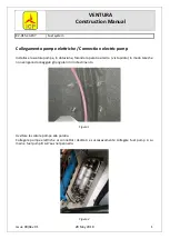
FIGURE 2: SOLDER WIRE TO PIN
FIGURE 1: INSERTING D-SUB PINS
15 PIN D-SUB
CONNECTOR
PLUG-IN
SIDE
PIN
INSERTION
SIDE
PIN 1
FEMALE D-SUB
PIN 1
MALE D-SUB
PIN INSERTION SIDE
WIRE INSULATION
BARREL
WITNESS HOLE
STRIPPED WIRE
5/32
5.21 ELECTRICAL
ELECTRICITY
There are three primary units of measure or terms to know to successfully wire the aircraft: voltage, current and power. The battery
we will be dealing with is known as a 12V battery. Batteries in good charge will have a terminal voltage between approximately 12.8
and 13 volts. When a battery is installed in an airframe and the alternator or generator is operating, the system voltage will be 14 to
14.5 volts. The second term is current which is measured in units of amps (A). Current is a value representing the flow of electrons
through a wire. An analogy would be a measurement of the flow of fuel to the engine in gallons/hour. The amount of current (amps)
flowing in a circuit will determine the size of the circuit breaker (or fuse), the type of switch to use and the size of wire to use. The
last term we must understand is power, more specifically the power being consumed by a circuit, which is measured in units of
Watts (W). Items such as lights are typically rated in watts.
WIRING
Stranded wire is preferred over a solid conductor. Solid conductor wire (a single strand of wire) is more susceptible to breakage
from the normal vibrations of an aircraft. Automotive type wire can be used in most applications. The only exception would be where
shielded wire is desired.
Wire should be supported such that it does not sag or swing freely. When passing through a bulkhead, use a grommet or support
the wire in the center of the hole with clamps to prevent chaffing which could result in an in-flight electrical short. Bundling wires
together is acceptable, except when a noisy wire is included with a sensitive circuit. An example of this would be including the
transponder antenna lead or a strobe power lead in the same bundle with the mike wire or headset leads. The impulses created by
either the transponder or the strobe could be picked up by the audio wiring.
WARNING: Antennas must be hooked up before turning on the transponder or radio or damage may result. Refer to the
transponder, radio, and antenna manual/installation instructions for more information.
Wire colors are called out in the building plans as needed. Wire call outs are followed by their color in brackets.
(WIRE COLOR/STRIPE COLOR). Colors are abbreviated as follows: BLK = BLACK, BLU = BLU, BRN = BROWN, GRN = GREEN,
GRY = GRAY, ORN = ORANGE, PRP = PURPLE OR VIOLET, RED = RED, WHT = WHITE, YEL = YELLOW. Harnesses are
supplied with multi-colored wire or white wire with a label.
REPAIRING D-SUB PINS
If the proper crimping tool is unavailable, machined d-sub pins and sockets
may be soldered on. If unfamiliar with soldering it may be prudent to practice
this procedure on a sample wire before repairing the flight article wire.
Step 1: Strip wire back per the dimension in Figure 2.
Step 2: Tin the end of the stripped wire by heating up the wire as it exits the
insulation while holding solder against the tip of the wire. When the solder
wicks into the strands of the stripped wire remove the heat and solder. It is
very important to not let the solder wick beyond the end of the exposed
wire under the insulation. This will make the wire brittle, fatigue and
break where it exits the back of the pin.
Step 3: Slide the tinned portion of the wire fully into the pin or socket. Use a
soldering iron to heat the barrel of the pin or socket while inserting solder wire
into the witness hole (This will require a solder wire of a small diameter). Melt
solder into the witness hole, then remove the heat and solder. Be careful not
to get excess solder on the barrel of the pin or socket
Step 4: Check that the wire is properly soldered to the pin by gently pulling on
the pin or socket and the wire.
PAGE
REVISION:
DATE:
VAN'S AIRCRAFT, INC.
04/15/13
2
RV-ALL
05-19