4.6
CONTROLS
Before starting to work, all operators should familiar-
ize themselves with the location and function of the
controls on the tractor and machine as appropriate.
1. PTO Control Lever: On tractor.
2. Throttle: On tractor.
3. Hydraulic Controls: On tractor.
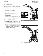
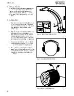
4. Spout Deflector:
Move lever (A) up to release deflector and allow
the material to be blown as far as possible. Pull
lever down to have deflect for direct material
close to grinder. On optional hydraulic
chute,
controls are on tractor.
5. Spout Lock: Pull lever (B) down to retract lock
pin from mounting flange. Push up to insert pin
into flange and lock spout in position.
6. Winch (C): Turn handle clockwise to spring load
baffles on tub wall. Turn counter-clockwise to
retract baffles. Secure winch with locking
lever on cable side of winch.
OPERATION
18
A
B
C
Fig. 3 CONTROLS ON STANDARD CHUTE
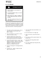
Fig. 4 HYDRAULIC CHUTE
Summary of Contents for H Series
Page 1: ...ROUND BALE GRINDER MODEL H OPERATOR S MANUAL AND PARTS BOOK INC FARM EQUIPMENT MANUFACTURER...
Page 6: ...2...
Page 31: ...Fig 23 MANGER FEEDING OPERATION 27...
Page 34: ...OPERATION 30...
Page 46: ...SERVICE MAINTENANCE 42...
Page 52: ...7 4 HYDRAULIC CIRCUIT SPECIFICATIONS 48 GRATE CYLINDERS TO TRACTOR...
Page 53: ......
Page 66: ...H C R PPE PPER CH 16 8 7 10 9 11 4 15 14 1 13 12 2 6 5 3 17 CUVE TUB D 9 10 17 18 19...
Page 69: ...1 5 9 2 3 4 6 8 17 CHUTE MANUELLE MANUAL CHUTE E 7 7 6 2...
Page 75: ...1 3 5 2 4 17 CHUTE MANUELLE D FLECTEUR MANUAL CHUTE DEFLECTOR H 6 6 4 2 8 10 12 9 7 9 11...
Page 78: ......
Page 79: ......
Page 80: ......
Page 81: ......
Page 82: ......
Page 83: ......
Page 84: ......
Page 85: ......


