ICON10 / ICON1 (Continued)
Configure Network
26. Set percent timer to 0% to keep machine from
moving.
27. Verify that all valves are powered up.
Follow the pipeline and look at the LED on each
valve to confirm that it is blinking green. If not,
check the connection to and from the valve.
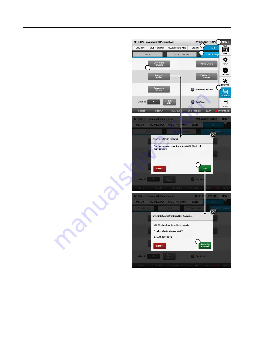
28. Configure the valve network. See Figure 42-1.
(a) Push
Menu
,
Programs
,
VRI
, and
VRI-iS
Diagnostics
button to display the VRI-iS
Diagnostics screen. See Figure 42-1.
(b) Push the
Configure Network
button to dis-
play the Configure VRI-iS Network screen.
(c) When prompted to initiate VRI-iS network
configuration, push the
Yes
button.
(d) Wait for network configuration to complete.
When configuration is complete the VRI-iS
Network Configuration Complete screen will
be displayed.
(e) Compare the number of valves configured to
the number of valves on the Sprinkler Chart
that were entered in step 15.
• If more valves were configured than were
entered, go back to step 15 and enter the
installed number of valves.
• If fewer valves were configured than en-
tered, push the
Reconfig Network
button.
If the result is the same, continue with Test
Valve Operation on the next page.
1
2
3
4
5
6
7
Figure 42-1 1. Menu
2. Programs
3. VRI
4. VRI-iS Diagnostics
5. Configure Network
6. Yes
7. Reconfig Network
42
Setup
Summary of Contents for VRI-iS
Page 2: ...2 This page was left blank intentionally...
Page 44: ...This page was left blank intentionally 44 Setup...
Page 50: ...50 Field Install and Wiring Diagrams VRI iS Power Supply Tower Box Field Install pn 9312421...
Page 51: ...51 Field Install and Wiring Diagrams VRI iS Power Supply Tower Box Wiring Schematic pn 0999334...
Page 52: ...52 Field Install and Wiring Diagrams VRI iS GPS Position Tower Box Field Install pn 9312419...
Page 53: ...53 Field Install and Wiring Diagrams VRI iS GPS Position Tower Box Wiring Schematic pn 0999346...
Page 82: ...82 Troubleshooting This page was left blank intentionally...
Page 102: ...102 Parts This page was left blank intentionally...


